Elevated open-center transit guideway with open-mesh screen emergency walkway

a transit guideway and open-center technology, applied in the field of transit systems, can solve the problems of no provision for passengers to disembark, no provision for and substantial obstruction of sunlight to the ground below

Inactive Publication Date: 2002-11-07
HENDERSON J KIRSTON
View PDF0 Cites 44 Cited by
  • Summary
  • Abstract
  • Description
  • Claims
  • Application Information

AI Technical Summary

Problems solved by technology

However, generally an elevated system creates a substantial obstruction to sunlight to the ground below.
These systems result in a dead zone to the

Method used


Image

  • Elevated open-center transit guideway with open-mesh screen emergency walkway
  • Elevated open-center transit guideway with open-mesh screen emergency walkway
  • Elevated open-center transit guideway with open-mesh screen emergency walkway

Examples


Embodiment Construction

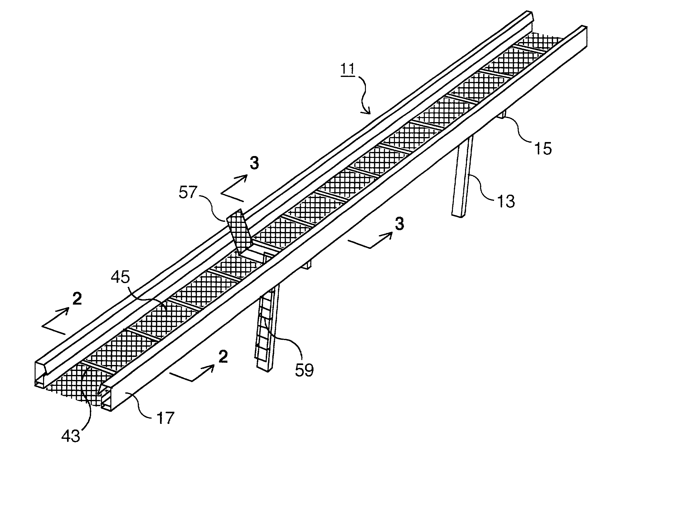
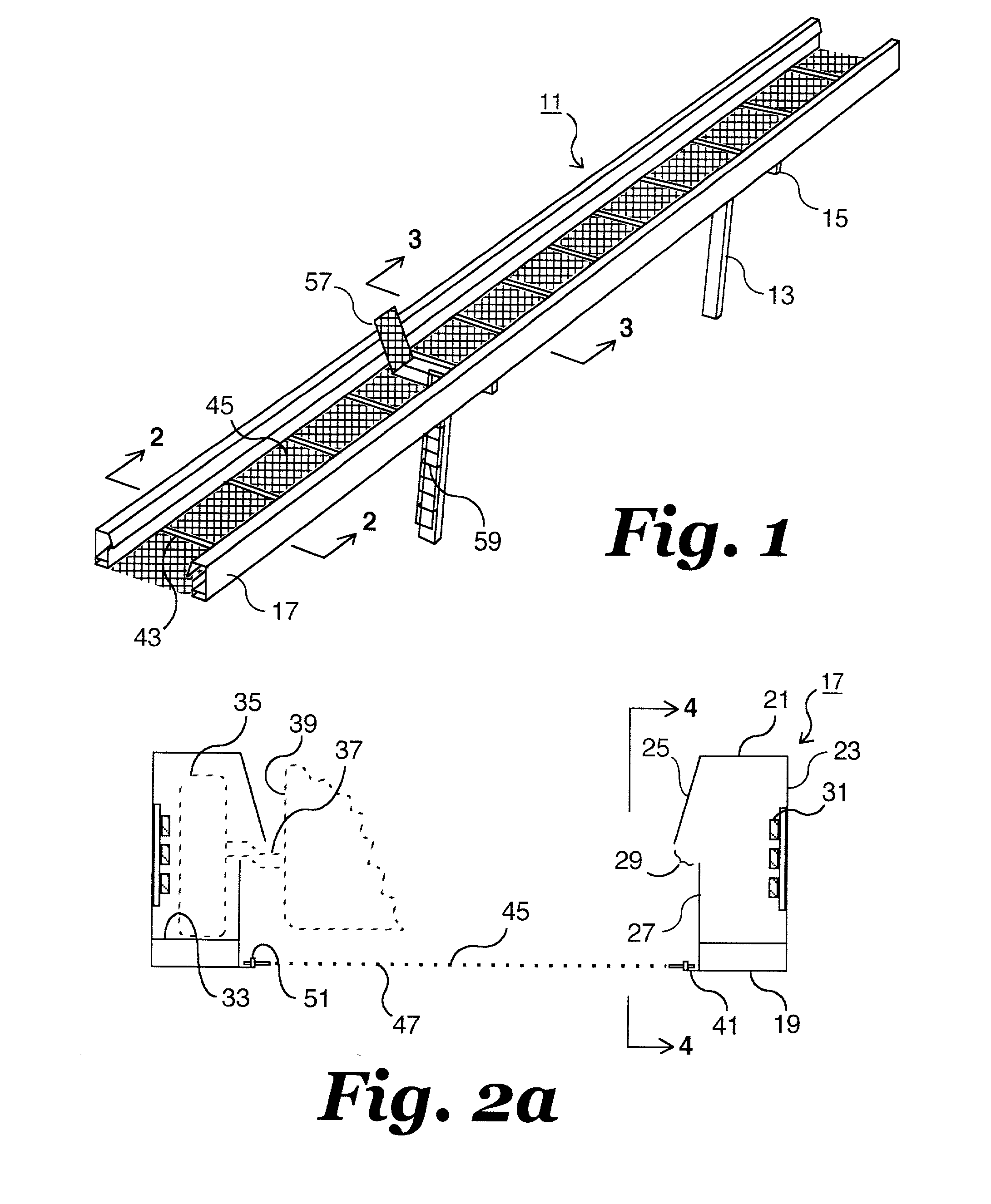
[0014] Referring to FIG. 1, transit system 11 has a plurality of vertical columns 13 that are supported in the ground. Columns 13 are spaced apart, and each column 13 has a cross member 15 at its upper end. A pair of guideways 17 are supported on cross members 15.

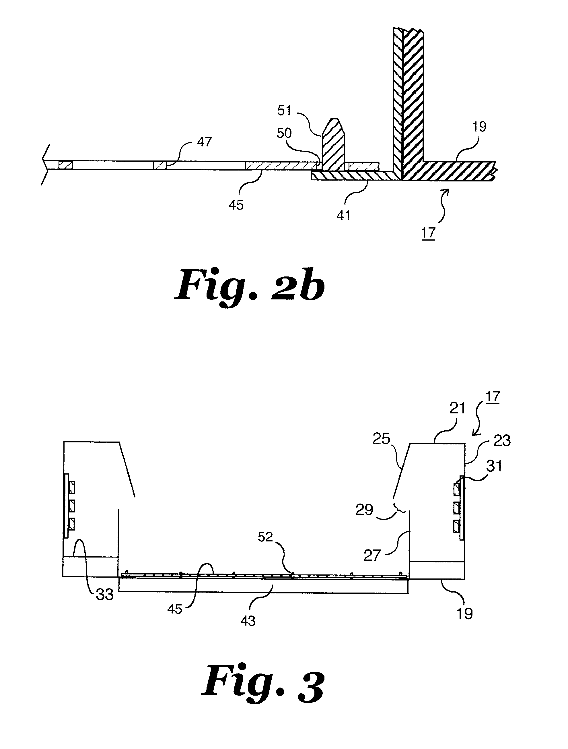
[0015] Referring to FIG. 2, guideways 17 preferably are hollow, longitudinally extending members. Each guideway 17 has a bottom 19, a top 21 and an outer side wall 23. An inner side wall has an upper portion 25 and a lower portion 27. Upper portion 25 inclines downward and inward from top 21. Lower portion 27 extends upward vertically, parallel with outer side wall 23. Upper portion 25 thus overhangs the upper edge of lower portion 27. This results in a longitudinally extending slot 29 that is about midway between bottom 19 and top 21. Electrical power and control lines 31 are located within guideway 17, preferably on the inside of outer sidewall 23. A track 33 may be located above bottom 19 creating a space above bottom 19...


PUM


Abstract

An elevated transit system has a pair of spaced apart guideways for supporting a vehicle. The guideways are supported on vertical columns above the ground. An emergency walkway extends between the guideways The walkway has a plurality of apertures to allow the passage of sunlight to the ground below.

Description

[0001] This application claims the benefit of provisional application 60 / 281,963, filed Apr. 6, 2001.1. FIELD OF INVENTION[0002] This invention relates in general to a transit system having a pair of spaced-apart guideways for receiving wheels of a vehicle and an open-mesh walkway located between the guideways for allowing passengers to disembark from the transit system in the event of a malfunction.2. BACKGROUND OF THE INVENTION[0003] This invention deals with transit systems that elevate a passenger vehicle as well as automatically control the operation of the vehicle, such as monorails as well as systems where vehicles roll on a guideway. An advantage of an elevated transit system is that it does not interfere with conventional vehicles located on the ground. However, generally an elevated system creates a substantial obstruction to sunlight to the ground below. Also, an elevated system should have an emergency walkway for passengers to disembark in the event of a malfunction. If...

Claims


Application Information

Patent Timeline
IPC IPC(8): E01B25/10E01B25/28
CPCE01B25/28E01B25/10
Inventor HENDERSON, J. KIRSTON
Owner HENDERSON J KIRSTON
Why Eureka
Try Eureka