
Transport system evaluator

a technology of transport system and evaluator, which is applied in the field of evaluating apparatuses, can solve problems such as difficulty in identifying the problem and its location, system components that may operate improperly, and parts such as bearings, guide components, and drive wheels may become misaligned or damaged undetected,

Active Publication Date: 2010-09-30
UNITED PARCEL SERVICE OF AMERICAN INC
View PDF65 Cites 79 Cited by
  • Summary
  • Abstract
  • Description
  • Claims
  • Application Information

AI Technical Summary

Benefits of technology

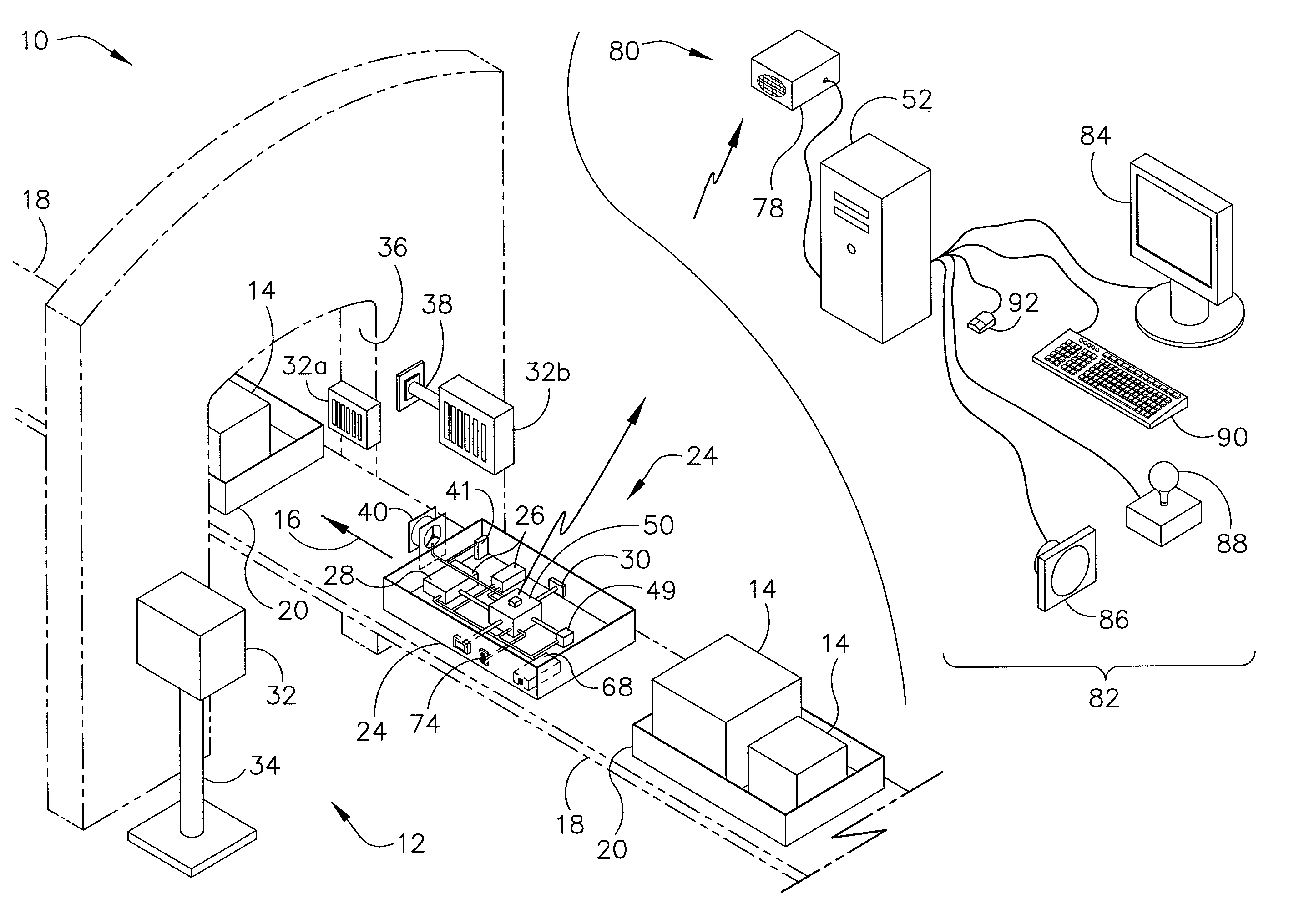
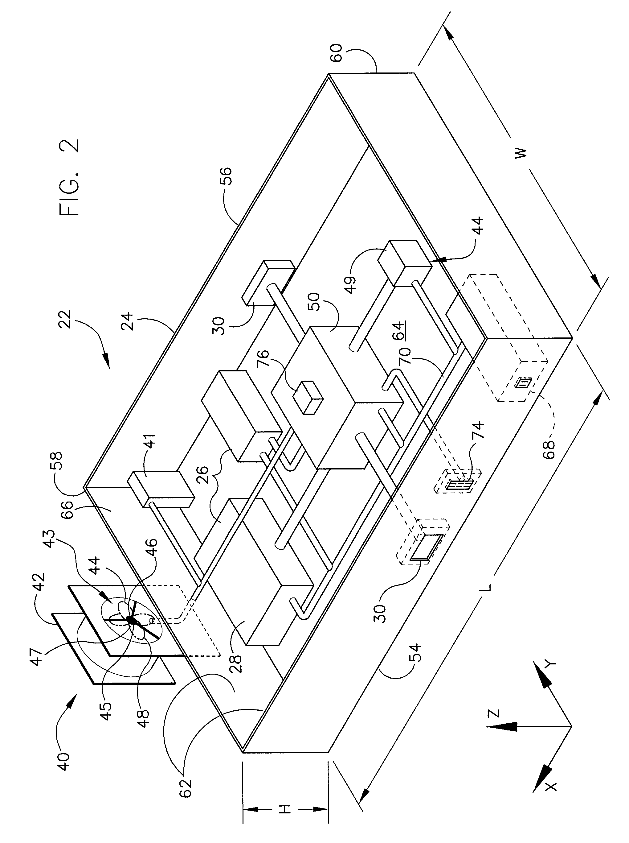
[0007]Various embodiments of the present invention relate to an evaluating apparatus arranged to evaluate an item-transport system having a flow path. The apparatus includes one or more position markers adjacent the path and an evaluating device for sensing the markers and conditions of the transport system. The evaluating device has at least one evaluation sensor configured to (A) sense conditions of the transport system and (B) produce evaluation-sensor data based on the sensed conditions. The evaluating device also has a position-marker sensor configured to sense the position markers and produce position-marker data. The apparatus further includes a distance meter configured to produce distance data and at least one computing device configured to determine a particular location at which the evaluating device was along the path of the item-transport system when a particular condition of the item-transport system was sensed based on the evaluation-sensor data, the position-marker data, and the distance data.
[0008]Some embodiments of the present invention relate to a method for evaluating an item-transport system utilizing an evaluating apparatus including (i) one or more position markers positioned adjacent a flow path of the item-transport system, (ii) an evaluating device including at least one evaluation sensor and a position-marker sensor, (iii) a distance meter, and (iv) at least one computing device. The method includes transporting the evaluating device along the flow path through the item-transport system and sensing the position markers utilizing the position-marker sensor as the evaluating device is transported along the flow path to produce position-marker data. The method also includes measuring utilizing the distance meter at least one parameter selected from a group of parameters consisting of distance traveled by the evaluating device and speed of the evaluating device. The method also includes producing distance data based on the measured parameter. The method further includes determining in the computing device a particular location of the evaluating device along the flow path of the item-transport system at which a particular condition of the one or more conditions was sensed by considering the distance data, the evaluation-sensor data, and the position-marker data.

Problems solved by technology

Throughout such systems, and especially at interface points, system components from time to time operate improperly due to being misaligned or damaged.
Parts such as bearings, guide components, and drive wheels may become misaligned or damaged undesirably by normal wear over time or improper loading.
Because components operating improperly are often located in areas of limited access, it is often difficult to identify the problem and its location.
Problems in the package-handling system are often in far reaches of the system.
Having the system down for a few hours or much longer for maintenance on these occasions may be very costly.
It is also costly to repair more parts of the package-handling system then necessary in cases where the particular problem and / or facility or area in which the flow path is located area has not been pinpointed.
At early stages, though, slight vibrations or other indications of improper function are difficult or impossible to detect by casual observance.
Even when problems are observable by a visual inspection, or identified using handheld sensors, it is a time consuming and costly endeavor for personnel to regularly walk around the entire system, which may be many miles long.
Manually monitoring item-transport systems, such as package-handling systems, on a continuous basis using people constantly inspecting the system may also be expensive.
Moreover, personnel often cannot see certain aspects of the package-handling system during operation of the system, such as within tunnels or within other equipment of the package-handling systems through which packages move while being handled.
Also, some portions of package-handling systems are not easily accessible by personnel and are preferably accessed only to upgrade equipment or fix a known problem.

Method used


Image

  • Transport system evaluator
  • Transport system evaluator
  • Transport system evaluator

Examples


first embodiment

[0017]Referring to the figures, and more particularly to FIG. 1, an evaluating apparatus according to the present invention is designated by reference number 10. The evaluating apparatus 10, or evaluator, may be used to monitor a variety of transporting systems 12 without departing from the scope of the present invention. For example, as primarily described herein, the evaluating apparatus 10 may be used to monitor a system 12 handling items such as mail parcels or packages 14.

[0018]Although the evaluating apparatus 10 is primarily described in connection with such package-handling systems 12, the evaluating apparatus 10 is not limited to such use and may be used to evaluate other systems of transport. The techniques and apparatus 10 described herein may be used in other contexts, such as to evaluate systems transporting other items. For example, the techniques and apparatus 10 may be used to evaluate a luggage-handling system or a material-handling system such as those used to tran...

second embodiment

[0132]In the second embodiment for processing time and marker data to determine time elapsed since the evaluating device 22 passed a marker 32 and the identity of that marker (item (ii), above), the timing unit 40 provides to the local computing device 50 time data including a continuous count from an introduction of the evaluating device to the package-handling system 12. In this embodiment, the position-marker sensor 30 provides to the local computing device 50 updated position-marker data reflecting the most recent position marker sensed by the evaluating device 22.

[0133]The evaluating apparatus 10 of this second embodiment may be configured so that the timing unit starts counting (e.g., 1, 2, 3, etc.) once the evaluating device 22 is introduced to the package-handling system 12. For example, in some embodiments, the timing unit 40 starts counting once a user or device releases the evaluating device 22 into the system and flips a switch (not shown) to start the timer, or when a f...

third embodiment

[0136]In the third embodiment for processing time and marker data to determine time elapsed since the evaluating device 22 passed a marker 32 and the identity of that marker (item (iii), above), the timing unit 40 maintains a continuous count and sends time data corresponding to the count to the local computing device 50 upon receiving a signal from the local computing device or the position-marker sensor 30 that a position marker was sensed by the evaluating device 22. The timing unit 40 may also be adapted to provide the current count value upon receiving a signal from the accelerometer 28 or local computing device 50 that an acceleration of interest was sensed. The evaluating apparatus 10 may be configured to recognize a signal from the position-marker sensor 30, accelerometer 28, or local computing device 50 as a request for time data. The timing unit 40 may be configured to maintain the count by creating, or creating and storing, the count.

[0137]For example, if the evaluating d...


PUM


Abstract

An evaluating apparatus arranged to evaluate an item-transport system having a flow path. The apparatus includes one or more position markers adjacent the path and an evaluating device for sensing the markers and conditions of the transport system. The evaluating device has at least one evaluation sensor configured to (A) sense conditions of the transport system and (B) produce evaluation-sensor data based on the sensed conditions. The evaluating device also has a position-marker sensor configured to sense the position markers and produce position-marker data. The apparatus further includes a distance meter configured to produce distance data and at least one computing device configured to determine a particular location at which the evaluating device was along the path of the item-transport system when a particular condition of the item-transport system was sensed based on the evaluation-sensor data, the position-marker data, and the distance data.

Description

FIELD OF THE INVENTION[0001]Various embodiments of the present invention relate to evaluating apparatuses and, more specifically, to apparatus for evaluating conditions associated with a package-handling system or other item-handling and / or conveyor systems.BACKGROUND OF THE DISCLOSURE [0002]Package-handling systems, such as those having conveyor belts, drive and guide packages or package-carrying bins or trays through warehouses and delivery hubs. These systems are often thousands of feet long and have hundreds of joints or interface points, such as turns or changes in elevation. Throughout such systems, and especially at interface points, system components from time to time operate improperly due to being misaligned or damaged. Parts such as bearings, guide components, and drive wheels may become misaligned or damaged undesirably by normal wear over time or improper loading. Because components operating improperly are often located in areas of limited access, it is often difficult...

Claims


Application Information

Patent Timeline
Patent Type & Authority Applications(United States)
IPC IPC(8): G08B21/00H04B1/00G06K7/10
CPCG06Q50/30G06Q50/40
Inventor SMITH, STEVEN L.
Owner UNITED PARCEL SERVICE OF AMERICAN INC
Learn More