Point-to-multipoint digital radio frequency transport

a digital radio frequency transport and multi-point technology, applied in the field of high-capacity mobile communication systems, can solve the problems of significant interference in the forward path of signal splitting in the forward path, steel frame buildings, and inability to provide full coverage in these areas

Inactive Publication Date: 2009-12-29
GOOGLE LLC +1
View PDF57 Cites 169 Cited by
  • Summary
  • Abstract
  • Description
  • Claims
  • Application Information

AI Technical Summary

Benefits of technology

[0008]The above-mentioned problems with distributing RF signals within a building and other problems are addressed by the present invention and will be understood by reading and studying the following specification.

Problems solved by technology

One obstacle to providing full coverage in these areas is steel frame buildings.
Inside these tall shiny buildings (TSBs), signals transmitted from wireless base stations attenuate dramatically and thus significantly impact the ability to communicate with wireless telephones located in the buildings.
In passive RF distribution systems, signal splitting in the forward path is significantly limited due to inherent insertion loss associated with the passive devices.
Each split reduces the level of the signal distributed in the building thereby making reception, e.g. by cell phones, more difficult.
In addition, the high insertion loss of coaxial cable at RF frequencies severely limits the maximum distance over which RF signals can be distributed.
Further, the system lacks any means to compensate for variations of insertion loss in each path.
While down-conversion reduces insertion loss, the signals are still susceptible to noise and limited dynamic range.
Unfortunately, conventional systems using analog optical modulation transmission over optical fibers require highly sophisticated linear lasers to achieve adequate performance.
Also, analog optical systems are limited in the distance signals can be transmitted in the building.
Typically, this limitation is made worse due to the use of multimode fiber that is conventionally available in buildings.
In addition, analog installation typically includes significant balancing when setting up the system.
In addition, if the connectors are not well cleaned or properly secured, the RF levels can change.
One drawback with digitally transported RF in a point-to-point architecture is the equipment and cost requirement.
In particular, for use within a building or building complex the number of RF to digital interface devices and the fiber to connect these devices is burdensome.

Method used


Image

  • Point-to-multipoint digital radio frequency transport
  • Point-to-multipoint digital radio frequency transport
  • Point-to-multipoint digital radio frequency transport

Examples


Embodiment Construction

[0020]In the following detailed description of the preferred embodiments, reference is made to the accompanying drawings that form a part hereof, and in which is shown by way of illustration specific embodiments in which the invention may be practiced. It is to be understood that other embodiments may be utilized and structural changes may be made without departing from the scope of the present invention.

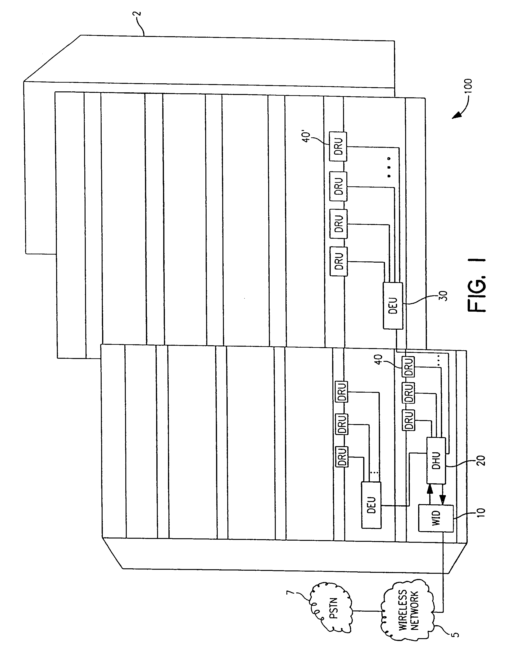
[0021]FIG. 1 is an illustration of one exemplary embodiment of a point-to-multipoint digital transport system shown generally at 100 and constructed according to the teachings of the present invention. The point-to-multipoint digital transport system 100 is shown distributed within a complex of tall shiny buildings (TSBs) 2. Although system 100 is shown in a complex of TSBs 2, it is understood that system 100 is not limited to this embodiment. Rather, system 100 in other embodiments is used to distribute signals in a single building, or other appropriate structure or indoor or outdo...


PUM


Abstract

A digital radio frequency transport system that performs bi-directional simultaneous digital radio frequency distribution is provided. The transport system includes a digital host unit and at least two digital remote units coupled to the digital host unit. The bi-directional simultaneous digital radio frequency distribution is performed between the digital host unit and the at least two digital remote units.

Description

CROSS REFERENCE TO RELATED APPLICATIONS[0001]This application is a continuation of U.S. application Ser. No. 09 / 619,431, filed Jul. 19, 2000, entitled “POINT-TO-MULTIPOINT DIGITAL RADIO FREQUENCY TRANSPORT”, which is incorporated herein by reference.TECHNICAL FIELD[0002]The present invention is related to high capacity mobile communications systems, and more particularly to a point-to-multipoint digital micro-cellular communication system.BACKGROUND INFORMATION[0003]With the widespread use of wireless technologies additional signal coverage is needed in urban as well as suburban areas. One obstacle to providing full coverage in these areas is steel frame buildings. Inside these tall shiny buildings (TSBs), signals transmitted from wireless base stations attenuate dramatically and thus significantly impact the ability to communicate with wireless telephones located in the buildings. In some buildings, very low power ceiling mounted transmitters are mounted in hallways and conference ...

Claims


Application Information

Patent Timeline
Patent Type & Authority Patents(United States)
IPC IPC(8): H04B7/14H04B10/00H04N7/173H04B7/26H04H60/72H04N7/26H04N7/52H04W4/06H04W4/12H04W4/14H04W8/02H04W8/16H04W8/20H04W24/00H04W40/22H04W80/06H04W84/12H04W88/02
CPCH04B10/25754H04N19/625H04W88/08H04B7/2606H04W4/06H04L51/28H04L51/38H03M7/4006H04L65/1006H04W4/14H04N19/139H04N19/109H04N19/91Y10S370/906Y10S370/907H04L65/1016H04L51/04H04W4/12H04W88/085H04W84/045H04B3/02H04L51/48H04L51/58H04L65/1104H04W72/30H04B10/25753H04Q11/0067H04Q2011/0047
Inventor WALA, PHILIP M.
Owner GOOGLE LLC
Why Eureka
Try Eureka