Specimen carrier for automated transport system and method and apparatus for identifying same

a technology of automatic transport system and specimen carrier, which is applied in the direction of charge manipulation, instruments, furniture, etc., can solve the problems of difficult to control the extent of the magnetic interrogation field of the reader, disadvantageous from the standpoint of manufacturing cost and complexity, and easily corrupted and even erased containers

Inactive Publication Date: 2002-02-05
COULTER INTERNATIONAL CORPORATION
View PDF6 Cites 186 Cited by
  • Summary
  • Abstract
  • Description
  • Claims
  • Application Information

AI Technical Summary

Benefits of technology

Yet another object of this invention is to provide an improved method and apparatus for identifying objects, such as the specimen carriers of the invention, moving together on a conveyor.
As a result of the invention, the manufacturing costs of container-carriers of the type described are significantly reduced, and an unambiguous identification of the carrier, or any other information carried by the carrier's RF tag is provided.

Problems solved by technology

While container carriers of the type disclosed in the above Canadian application might prove useful in transporting specimen containers in an automated transport system, these containers are disadvantageous from the standpoints of manufacturing cost and complexity.
Further, the suggested magnetic identification system, while plausible, is disadvantageous in that it can be readily corrupted, and even erased, by any significant field-generating stimuli in or near the conveyor system; thus, care must be exercised in the system design to provide proper shielding to prevent any magnetic structure in the area from interfering with the magnetic circuit between the carrier's embedded magnetic tag and the magnetic reader.
Further, in a magnetic system, it is difficult to control the extent of the reader's magnetic interrogation field, thereby making it difficult to unambiguously differentiate adjacent carriers on the conveyor.
Owing to the relatively large interrogation fields associated with such systems, they would be impractical for use in a miniaturized specimen conveyor system of the type described above.
More particularly, the RF interrogation field is so extensive that it would simultaneously energize multiple tags, making it difficult to selectively detect a single specimen among many other closely spaced specimens.
Moreover, due to the large loop area of the antennas used in such RF systems, large electromagnetic and electrostatic fields are produced which may affect devices outside the localized environments.
These large antennas are also susceptible to external noise typically present in the medical environment.

Method used


Image

  • Specimen carrier for automated transport system and method and apparatus for identifying same
  • Specimen carrier for automated transport system and method and apparatus for identifying same
  • Specimen carrier for automated transport system and method and apparatus for identifying same

Examples


Embodiment Construction

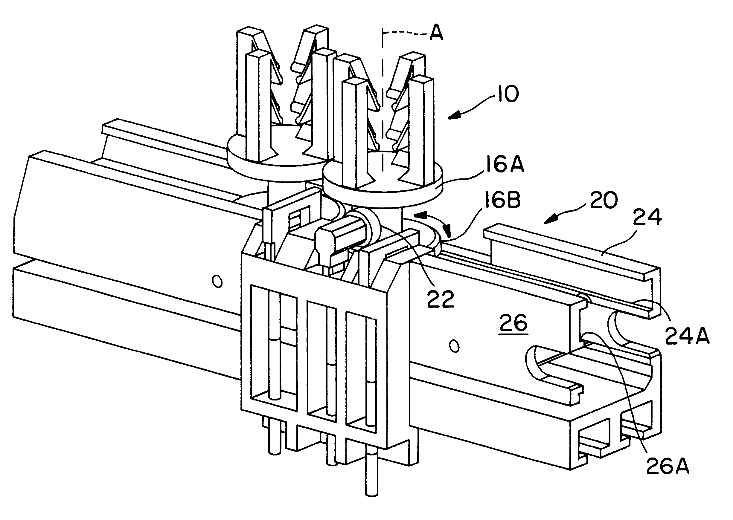
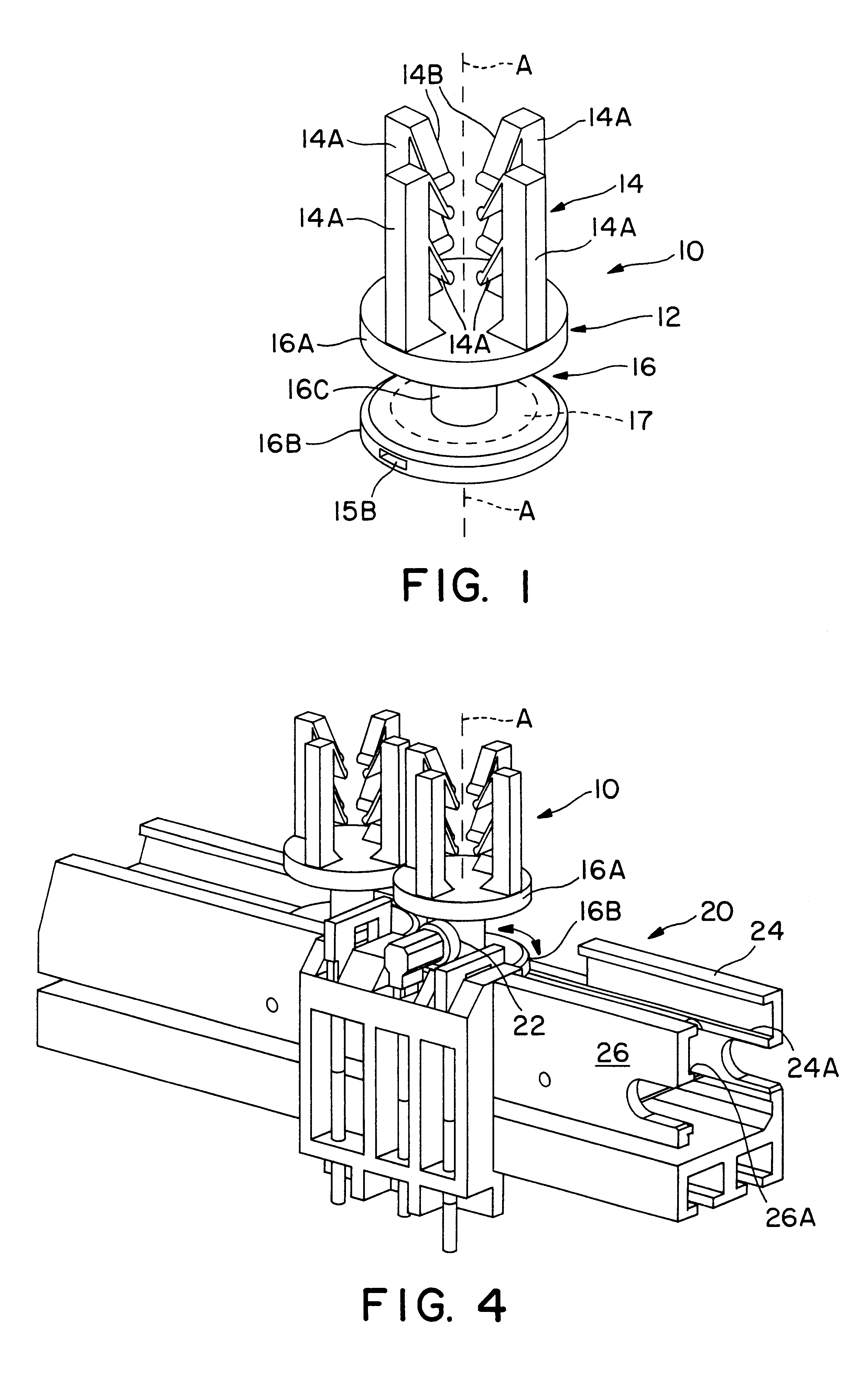
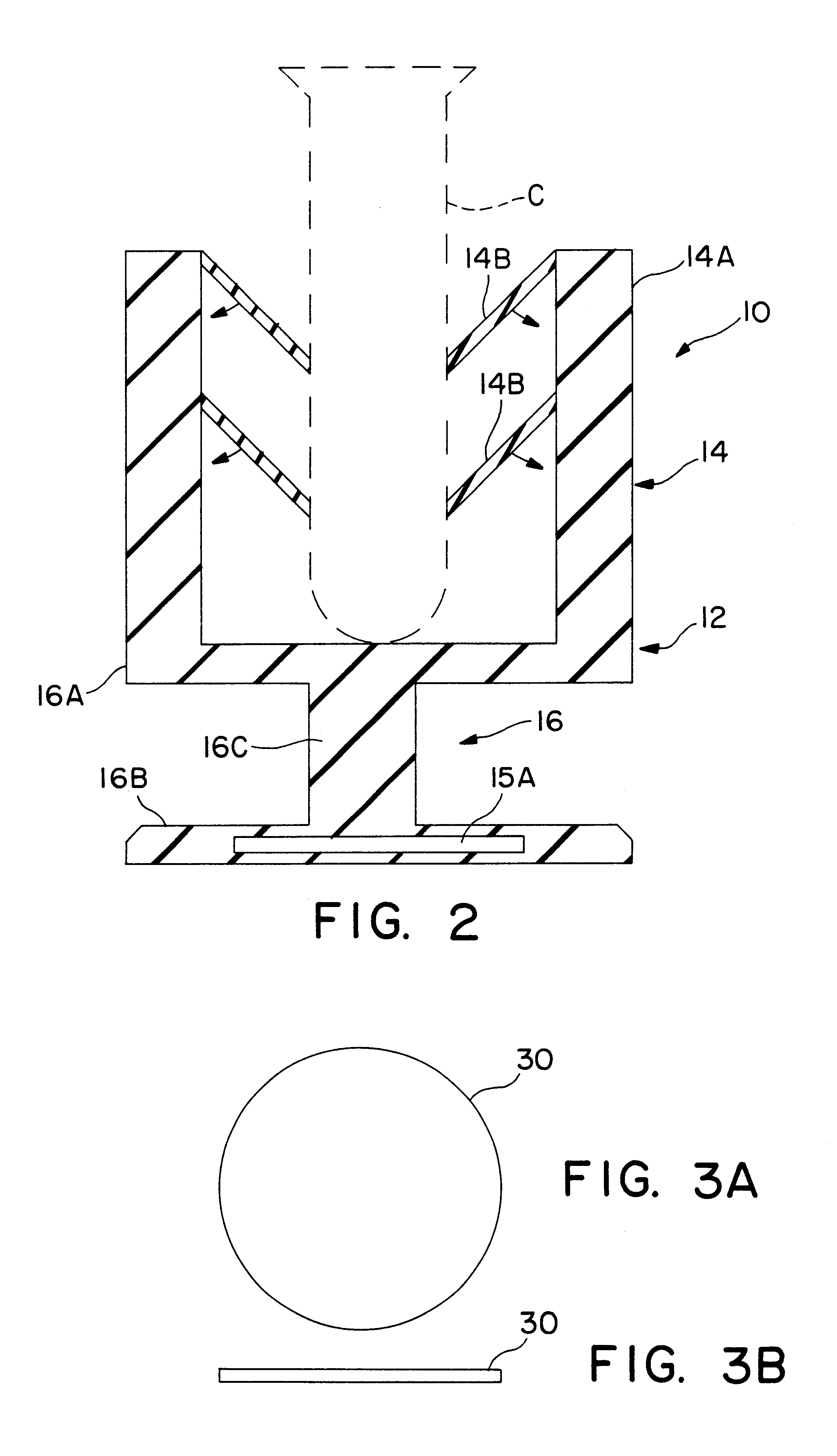
Referring now to the drawings, FIG. 1 illustrates a specimen carrier 10 adapted to be transported by an automated conveyor system while supporting a cylindrically-shaped specimen container, e.g. a test tube or vial, in a generally upright orientation. A portion of such conveyor system is shown in FIG. 4. Carrier 10 preferably comprises a unitary (i.e., one-piece) structure 12 defining (i) a container-retaining portion 14 for receiving, supporting and retaining a specimen container C (shown in FIG. 2) in an upright orientation; and (ii) a pedestal portion 16 adapted to be engaged and manipulated by certain components of the automated conveyor system for the purpose of advancing the carrier along a predetermined path and for selectively rotating the carrier about a central axis A so that, for example, a barcode label on the container or carrier can be more easily read by a barcode reader positioned along the transport path. The container-retaining portion 14 comprises a plurality of r...


PUM

PropertyMeasurementUnit
diameteraaaaaaaaaa
heightaaaaaaaaaa
heightaaaaaaaaaa

Abstract

A specimen carrier comprises a unitary structure for receiving and retaining a specimen container in an upright orientation. Such unitary structure is defined by a pedestal having upper and lower platforms connected by a stem. Extending upwardly from the upper platform is a plurality of rigid members which support a plurality of opposing flexible fingers adapted to engage and press upon the side wall of a specimen container received by the carrier. Preferably, the specimen carrier of the invention has a chamber formed therein for housing a pre-programmed, programmable or otherwise radio-frequency (RF) identification tag in the form of an RF transponder. Upon being energized by a suitable RF field provided by an RF reader antenna or sensor positioned adjacent the carrier's intended path of movement, the tag transmits a unique identification code, such code being received by the antenna or sensor and decoded by the reader.

Description

1. Field of the InventionThe present invention relates to automated conveying systems for transporting biological and chemical specimens and the like, e.g., vials of blood, along a predetermined transport path, e.g., from a loading station to a work station for analysis or processing. More particularly, this invention relates to improvements in specimen carriers adapted to be transported by a conveyor system while supporting a specimen container in a generally upright orientation, and to methods and apparatus for identifying such carriers as they are transported. Another aspect of this invention relates to methods and apparatus for identifying such carriers.2. Discussion of the Prior ArtAutomated systems for analyzing various properties of biological and chemical specimens are well known. In certain automated blood analyzing systems, for example, a conveyor belt or the like serves to transport individual containers (e.g., vials or test tubes) of blood along a predetermined path, and...

Claims


Application Information

Patent Timeline
Patent Type & Authority Patents(United States)
IPC IPC(8): B65G17/00G01N35/04
CPCB65G17/002G01N35/04G01N35/00732B65G2201/02B65G2201/0261G01N2035/0406G01N2035/00782G01N2035/00801
Inventor BRITTON, TED W.QUESADA, VALENTINVEINER, CRAIG
Owner COULTER INTERNATIONAL CORPORATION
Why Eureka
Try Eureka