Particle beam irradiation apparatus and particle beam irradiation method

a particle beam and irradiation apparatus technology, applied in the field of particle beam irradiation apparatus and particle beam irradiation method, can solve the problems of deteriorating irradiation accuracy, unable to supply to the selected irradiation device the beam matching its irradiation scheme, and suppressing the beam size of the beam transported, so as to ensure accurately judge, and ensure the effect of irradiation accuracy and safety

Active Publication Date: 2010-05-04
HITACHI LTD
View PDF21 Cites 168 Cited by
  • Summary
  • Abstract
  • Description
  • Claims
  • Application Information

AI Technical Summary

Benefits of technology

[0010]In the present invention, charged particle beams suitable for the irradiation method adopted for the selected irradiation device can be transported thereto in order to modify operating parameters of the charged particle beam generator according to the above irradiation method. Irradiation accuracy and safety can thus be ensured.
[0011]Preferably, the irradiation apparatus further has a detector for detecting a beam state of the charged particle beams extracted from the charged particle beam generator, and a judging device for judging whether the beam state that has been detected is normal, and modifies judgment parameters of the judging device according to the irradiation method adopted for the selected irradiation device. This makes it possible to accurately judge whether the charged particle beams transported to the selected irradiation device are suitable for the irradiation method adopted therefor.
[0012]According to the present invention, irradiation accuracy and safety can thus be ensured, even if the irradiation apparatus has the irradiation devices that use different irradiation methods.

Problems solved by technology

That is to say, in the scanning method that requires changing an irradiation position, energy, and other irradiation parameters in order while changing apparatus component data settings according to the particular dose distribution, if the beam intensity of the beam transported to an irradiation device is too great, this could deteriorate irradiation accuracy since it may become impossible to follow up changed apparatus component data settings.
In addition, since the scanning method uses narrow beams, there is a need to suppress the beam size of the beams transported.
For this reason, even when the conventional charged particle beam irradiation apparatus was provided with irradiation devices of different irradiation schemes such as scanning and passive scattering, it has been impossible to supply to the selected irradiation device the beams matching its irradiation scheme.

Method used


Image

  • Particle beam irradiation apparatus and particle beam irradiation method
  • Particle beam irradiation apparatus and particle beam irradiation method
  • Particle beam irradiation apparatus and particle beam irradiation method

Examples


first embodiment

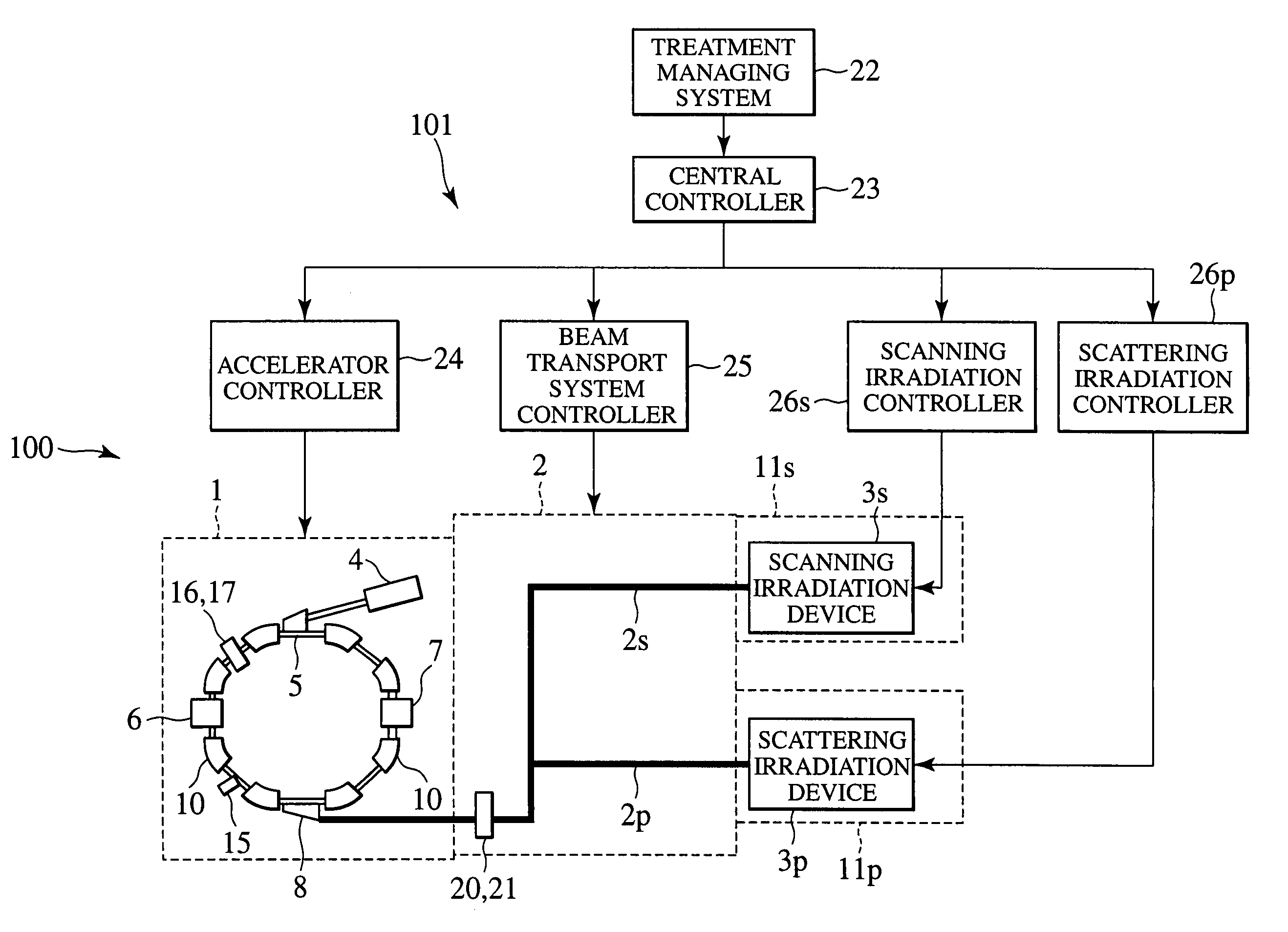
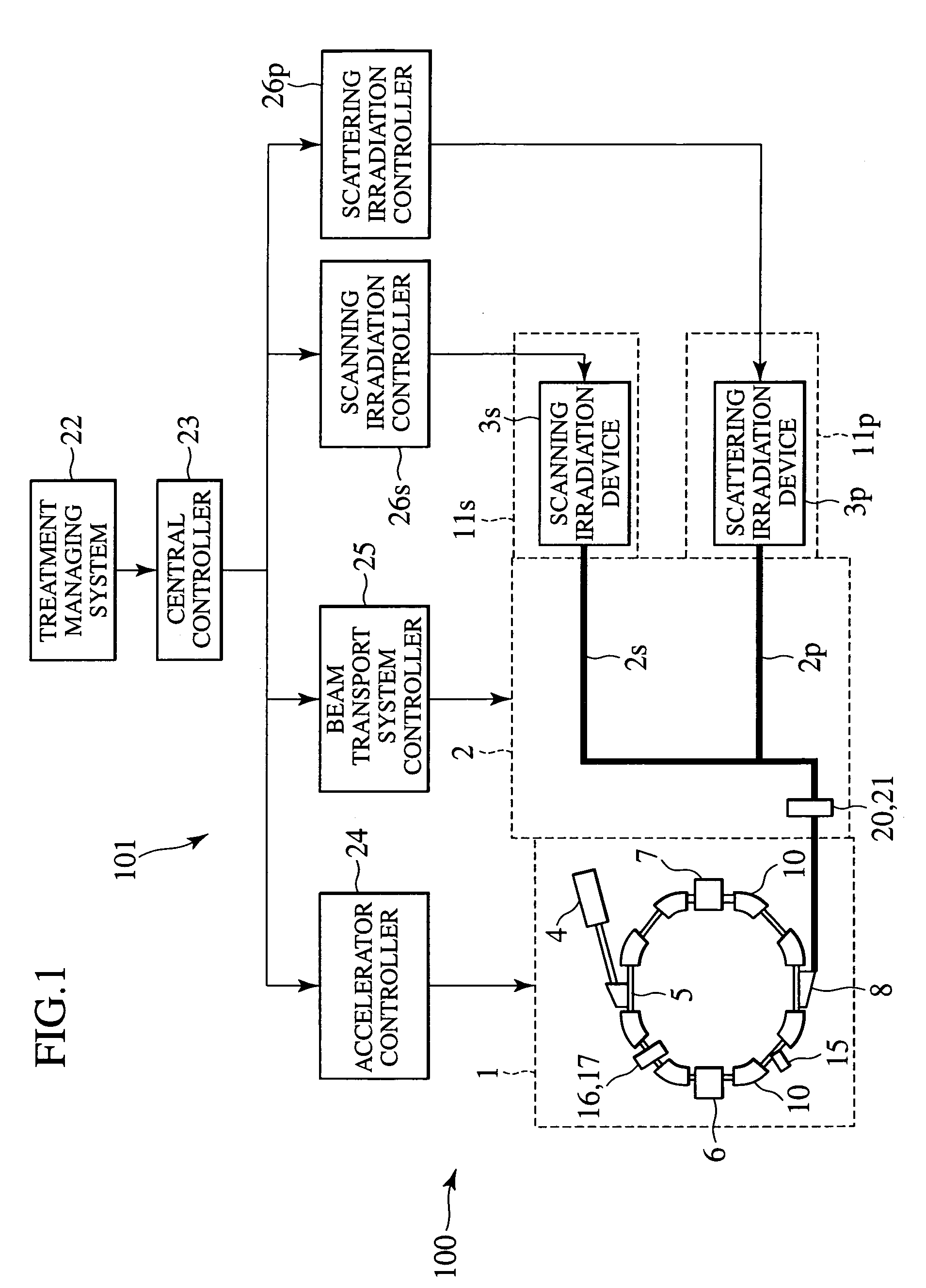
[0021]First, a charged particle beam irradiation apparatus that is a preferred embodiment of the present invention is described below using FIG. 1.

[0022]A charged particle beam irradiation apparatus 100 of the present embodiment has a charged particle beam generator 1, a beam transport system 2 connected to an output end of the charged particle beam generator 1, and two irradiation devices, 3s and 3p, that operate as irradiation field forming devices. More specifically, the charged particle beam irradiation apparatus 100 of the present embodiment is a proton beam irradiation apparatus.

[0023]The charged particle beam generator 1 has an ion source (not shown), a pre-accelerator (e.g., a linear accelerator) 4, and a synchrotron 5 that is a main accelerator. In the synchrotron 5, a high-frequency beam extraction device 6 formed with one pair of electrodes, and a high-frequency beam accelerating cavity 7 are installed on a circular revolution orbit of ion beams. A first high-frequency po...

second embodiment

[0054]A charged particle beam irradiation apparatus that is another embodiment of the present invention is described below using FIG. 6. Charged particle beam irradiation apparatus 100A of the present embodiment is adapted to include: a charged particle beam generator 1A with a cyclotron 5A, instead of the charged particle beam generator 1 with a synchrotron 5 in the charged particle beam irradiation apparatus 100; and a control system 101A with an added second passive scattering treatment room, an operational state monitoring device (judging device) 45, and an added second passive scattering irradiation controller for the added treatment room, instead of the control system 101 in the irradiation apparatus 100.

[0055]The charged particle beam irradiation apparatus 100A has the charged particle beam generator 1A equipped with the cyclotron 5A by which incident beams from an ion source (not shown) are accelerated to desired energy, a beam transport system 2A connected to an output end ...


PUM


Abstract

To ensure irradiation accuracy and safety, even when an irradiation device employing a different irradiation method is used, disclosed is herein a charged particle beam irradiation apparatus that irradiates an irradiation target with charged particle beams includes:a charged particle beam generator for generating the charged particle beams; a passive scattering irradiation device and a scanning irradiation device, both for irradiating the irradiation target with the charged particle beams; a beam transport system for transporting the charged particles beam extracted from the charged particle beam generator, to selected one of the two irradiation devices; and a central controller that modifies operating parameters on the charged particle beam generator, according to the irradiation method adopted for the selected irradiation device.

Description

BACKGROUND OF THE INVENTION[0001]The present invention relates to the particle beam irradiation apparatus and particle beam irradiation method used for irradiating affected regions with charged particle beams such as proton or carbon ion beams in order to provide medical care.[0002]Among known medical treatment methods is one in which the affected regions of patients who are suffering from diseases such as cancer are irradiated with proton, carbon ion, or other charged particle beams. The large-scale charged particle beam irradiation apparatus used in this treatment method has a charged particle beam generator, a beam transport system, and a plurality of irradiation devices. A charged particle beam that has been accelerated by the charged particle beam generator reaches selected one of the plural irradiation devices through the beam transport system, and then the beam is emitted from the nozzle of the irradiation device to the affected region of the patient lying on a treatment couc...

Claims


Application Information

Patent Timeline
Patent Type & Authority Patents(United States)
IPC IPC(8): A61N5/10
CPCA61N5/1043A61N5/1048A61N5/1079A61N2005/1087A61N2005/1074
Inventor MATSUDA, KOJIHIRAMOTO, KAZUOMORIYAMA, KUNIO
Owner HITACHI LTD
Why Eureka
Try Eureka