
Method and apparatus for broadcasting streaming video

a technology of streaming video and method, applied in the direction of color television details, two-way working systems, television systems, etc., can solve the problems of inability to achieve broadcasts to channels such as the internet, the inability to easily achieve broadcasts, and the inability to broadcast to various hand-held devices,

Inactive Publication Date: 2002-11-14
POPWIRE COM
View PDF19 Cites 136 Cited by
  • Summary
  • Abstract
  • Description
  • Claims
  • Application Information

AI Technical Summary

Problems solved by technology

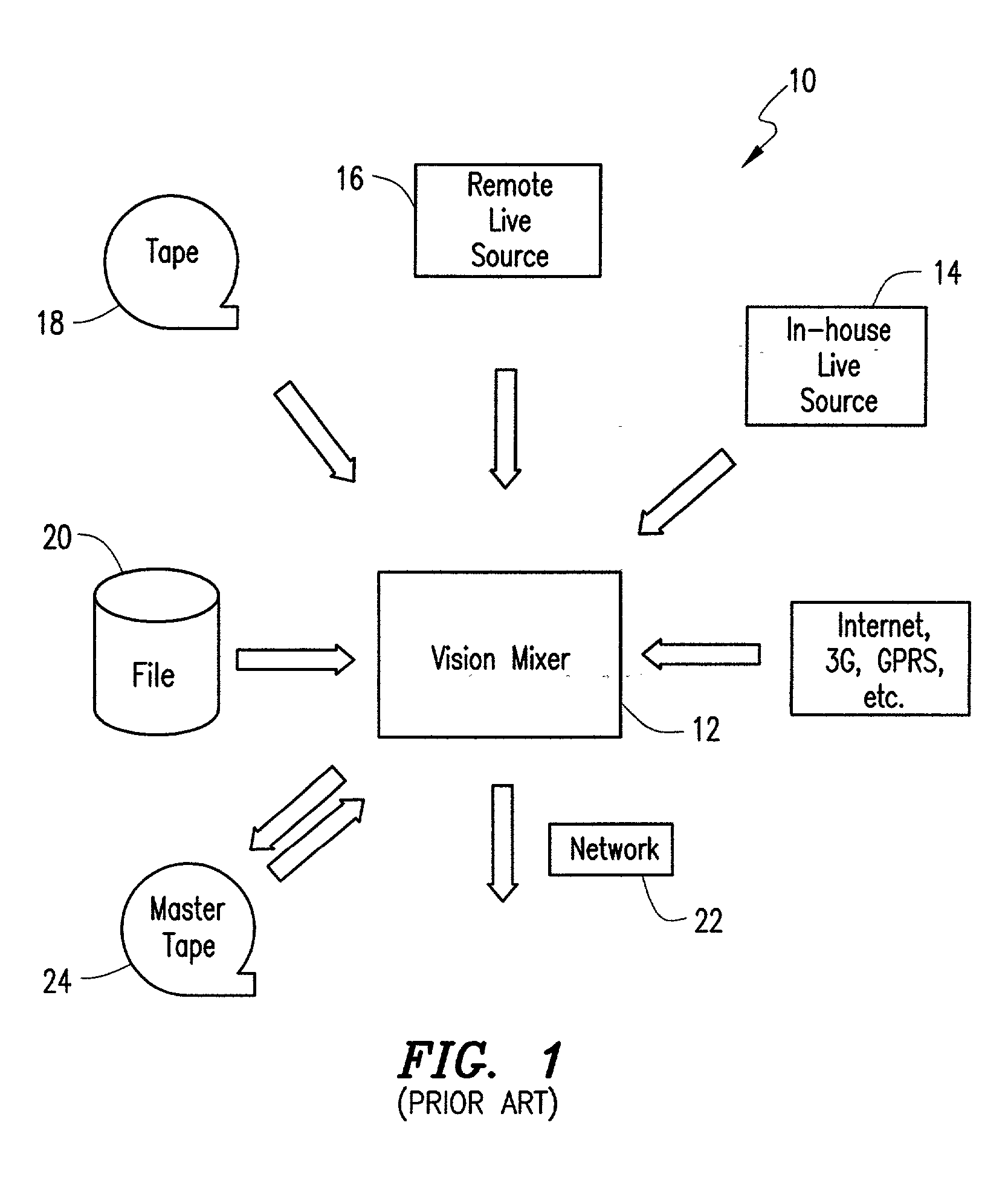
A conventional television production system, such as illustrated in FIG. 1, is limited in its capabilities.
Although some capabilities exist for broadcast over other channels, for example, webcast, using formats such as Quicktime, Real or Windows media, the ability to accomplish such broadcasts require several computers and video output cards and is very costly.
Broadcast to channels such as the Internet, the Mobile Internet and to various hand-held devices cannot be easily accomplished, if at all.
Current vision mixers are unable to support or control the different flows, and a director would have to work with a variety of different output formats to be able to broadcast to every channel.
This would put a great deal of strain on both the director and the system architecture, and every production would be costly and require significant man-hours to create.
In general, current TV broadcast technology does not allow video signals to be easily transmitted or received over the Internet.
Current vision mixers are not based on any standards and have no input interface for the Internet.
Significant limitations also exist with respect to the broadcast of video streams over the Internet.
Such a limitation significantly restricts effective utilization of the Internet as a broadcast medium.

Method used


Image

  • Method and apparatus for broadcasting streaming video
  • Method and apparatus for broadcasting streaming video
  • Method and apparatus for broadcasting streaming video

Examples


Embodiment Construction

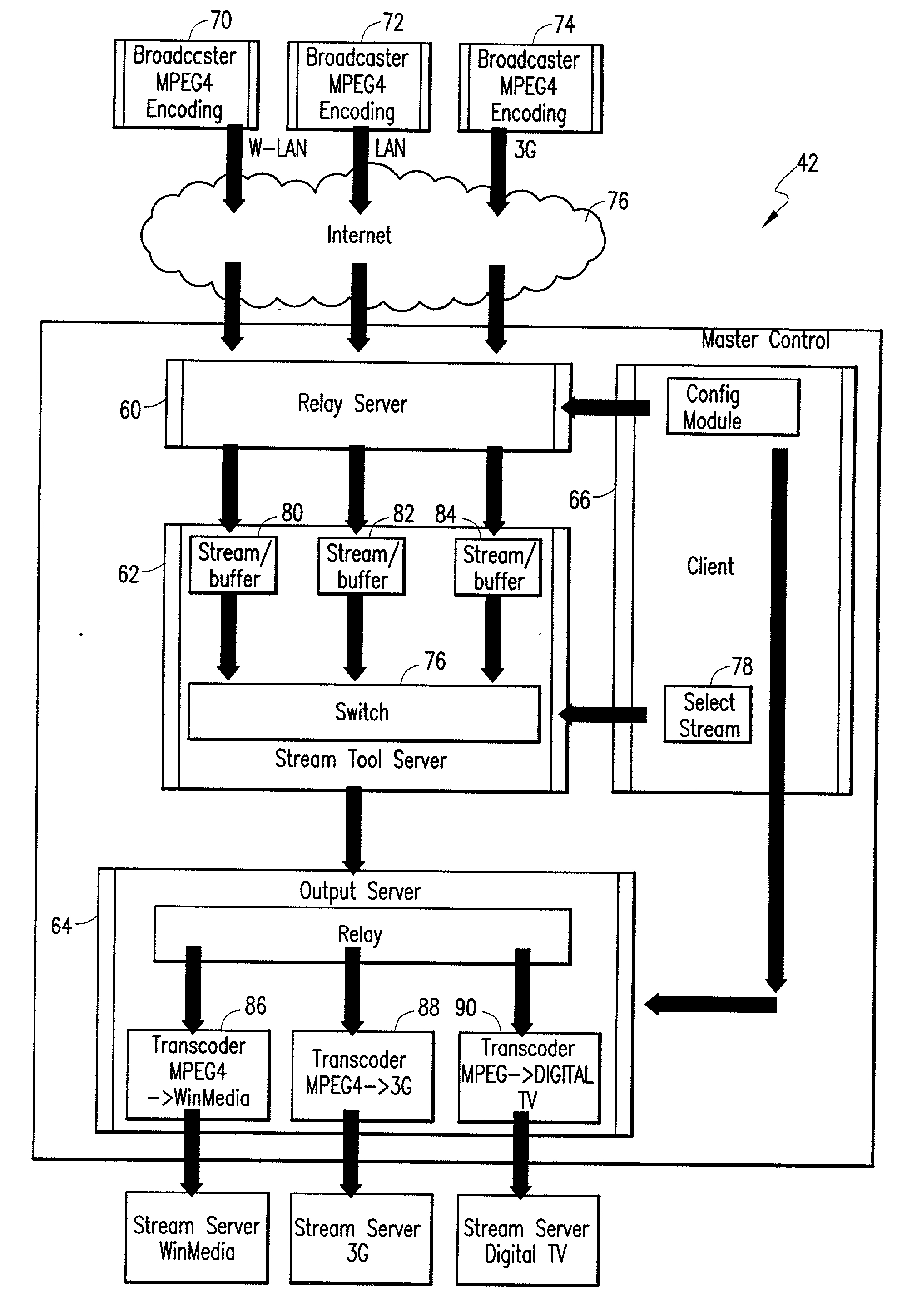
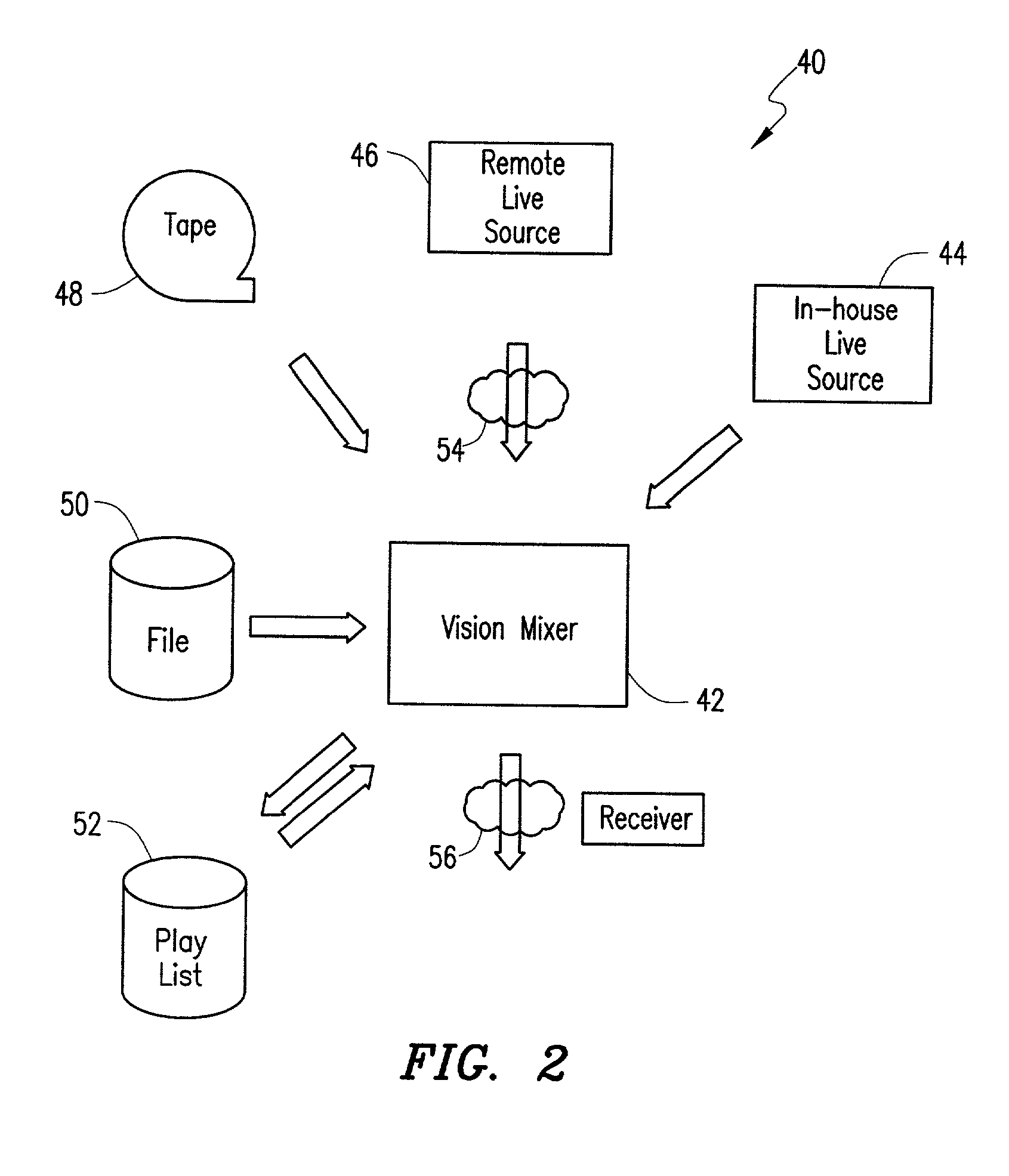
[0027] FIG. 2 is a block diagram that schematically illustrates a video production system according to a presently preferred embodiment of the present invention. The system is generally designated by reference number 40, and includes a master controller 42 that generally corresponds to the vision mixer utilized in a traditional television production system such as illustrated in FIG. 1. Master controller 42 receives video input streams from various sources such as a live in-house source 44, a remote live source 46, or from various archived materials such as a tape 48, a file 50 or a play list 52.

[0028] The video production system of FIG. 2 differs from system 10 of FIG. 1, however, in that the video streams input to the master controller 42 include video streams transmitted via the Internet or another IP-based network (generally referred to hereinafter as the Internet) as shown at 54, and the video stream output from the master controller 42 includes a video output stream broadcast ...


PUM


Abstract

Method and apparatus for broadcasting streaming video. A method for broadcasting streaming video according to the present invention has the steps of receiving a plurality of video input streams, each of the plurality of video input streams being transmitted via an IP-based network, selecting one of the plurality of video input streams for broadcast as a video output stream, and broadcasting the video output stream. The invention provides a technique by which any of a plurality of video input streams transmitted via the Internet or other IP-based network can be selectively broadcast in real time, and in which switching among the plurality of video input streams can be conducted in real time. The video output stream can also be broadcast over the Internet or other IP-based network such that a viewer can receive the various broadcasts on a PC or other device without re-connecting for each broadcast.

Description

[0001] This application claims priority from and the benefit of copending U.S. Provisional Patent Application Serial No. 60 / 278,193 filed on Mar. 23, 2001.[0002] 1. Field of the Invention[0003] The present invention relates generally to a method and apparatus for broadcasting streaming video. More particularly, the present invention relates to a method and apparatus for receiving a plurality of video input streams transmitted over the Internet or other IP-based network, and for selectively switching among the plurality of video input streams for selectively broadcasting the plurality of video input streams as single video output streams.[0004] 2. Description of the Prior Art[0005] FIG. 1 is a block diagram that schematically illustrates a television production system that is known in the art. The system is generally designated by reference number 10, and includes a vision mixer (or mixer board) 12 for processing video signals input thereto. Video input signals can include signals fr...

Claims


Application Information

Patent Timeline
IPC IPC(8): H04N5/44H04N21/234H04N21/2343H04N21/2662H04N21/2665H04N21/44H04N21/462H04N21/61
CPCH04N5/4401H04N21/23424H04N21/234309H04N21/6125H04N21/2665H04N21/44016H04N21/4622H04N21/2662H04N21/426
Inventor NORSTROM, ANDERSJOHANSSON, KAYKARLSSON, KENTPETERSSON, EMILKJELL, THOMAS
Owner POPWIRE COM
Learn More