Bevel stop for cutting device

Inactive Publication Date: 2003-02-06
BLACK & DECKER INC
View PDF0 Cites 36 Cited by
  • Summary
  • Abstract
  • Description
  • Claims
  • Application Information

AI Technical Summary

Benefits of technology

0004] Power-operated cutting devices such as, for example, miter saws and scroll saws, commonly include a work table or other work piece support structure and a cutting unit having a driven cutting element. In the case of a miter saw, for example, the cutting unit is a motor-driven circular saw blade. The cutting unit is movably mounted to the saw's work table by an attachment assembly and may be pivoted downward toward the work table in an arc substantially within a vertical plane. In this way, a work piece posit

Problems solved by technology

A dual bevel miter saw would be cumbersome and time-consuming to operate absent an easily engageable mechanism to reliably locate and secure the cutting unit at the vertical position.
Also, if a cut to be made at the 0.degree. bevel position is accidentally made with a slight leftward or rightward bevel, it may be necessary to scrap the workpiece.
Preferably, such mechanism is relatively s

Method used


Image

  • Bevel stop for cutting device
  • Bevel stop for cutting device
  • Bevel stop for cutting device

Examples


Example

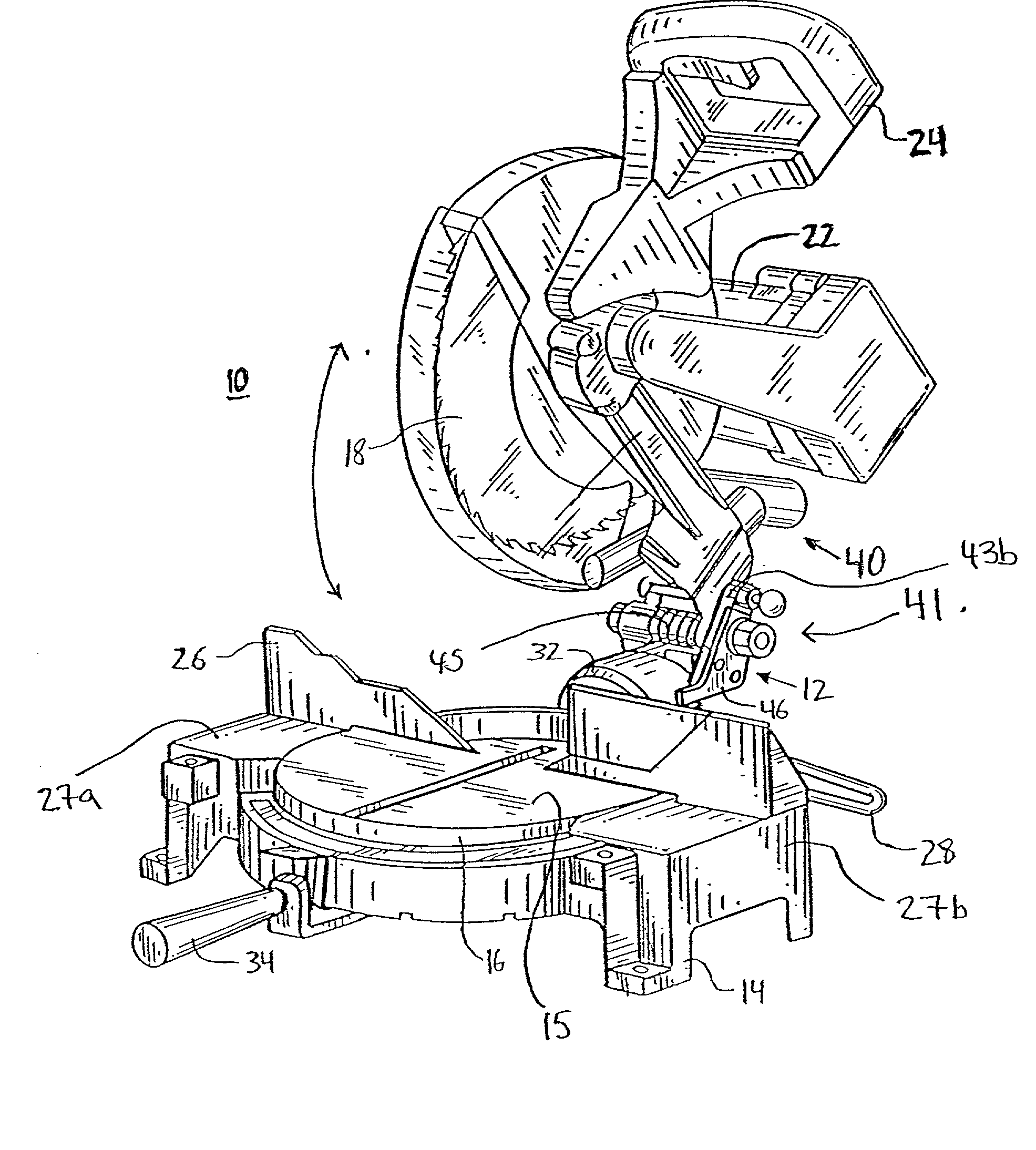
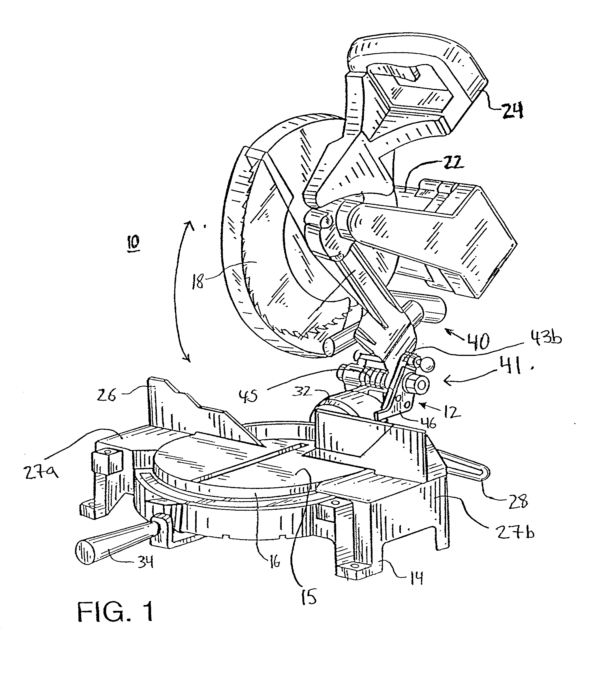
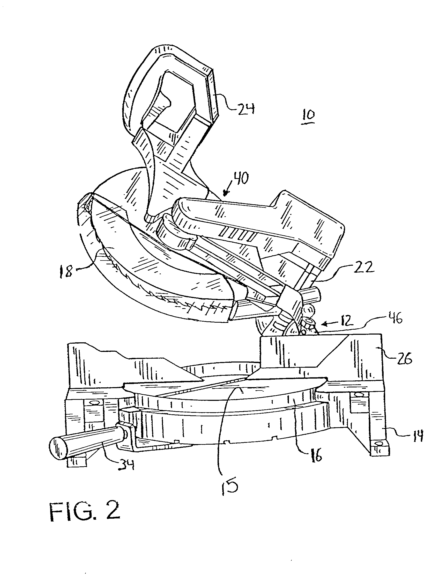
[0024] Referring now to the accompanying figures for the purpose of illustrating the invention and not for the purpose of limiting the same, there is shown in FIGS. 1 through 3 a dual bevel miter saw 10 that incorporates an embodiment of a bevel stop mechanism generally indicated as 12 constructed according to the present invention. The miter saw 10 includes a base 14 that supports a work table 16. The work table 16 includes a workpiece support surface 15 on which a workpiece may be supported during cutting operations. A fence 26 is mounted on side portion 27a and 27b of base 14. The fence 26 is adapted to further support a workpiece disposed on the workpiece support surface 15.

[0025] A cutting unit 40 is operably connected to the work table 16 in the manner described below. The work table 16 is rotatably mounted within the base 14 about a generally vertical axis (when the miter saw 10 is disposed on a generally horizontal surface) to permit adjustment of the miter angle of the cutt...


PUM

PropertyMeasurementUnit
Elevationaaaaaaaaaa

Abstract

A cutting device, such as a beveling miter saw, includes a base, a work table supported on the base, and a cutting unit operably connected to the base. The work table includes a workpiece support surface and a stop portion. The cutting unit is selectively rotatable about a first axis between leftward and rightward bevel positions relative to the workpiece support surface. A rotatable stop member is coupled to the cutting unit and is selectively rotatable relative to the cutting unit to selectively contact the stop portion to thereby prevent rotation of the cutting unit in one direction about the first axis. The rotatable stop member and the stop portion may be positioned so that those elements contact when the cutting unit is at a predetermined bevel position, such as a vertical (0°) bevel position, relative to the workpiece support surface.

Description

[0001] 1. Field of the Invention[0002] The present invention relates to a power-operated cutting device including a movable cutting unit. The present invention more particularly relates to power-operated cutting device including a mechanism for selectively positioning a cutting unit of the device at a predetermined position relative to a workpiece support of the device. The present invention finds application in various cutting devices including, for example power-operated miter saws, scroll saws, and drill presses.[0003] 2. Description of the Invention Background[0004] Power-operated cutting devices such as, for example, miter saws and scroll saws, commonly include a work table or other work piece support structure and a cutting unit having a driven cutting element. In the case of a miter saw, for example, the cutting unit is a motor-driven circular saw blade. The cutting unit is movably mounted to the saw's work table by an attachment assembly and may be pivoted downward toward th...

Claims


Application Information

Patent Timeline
IPC IPC(8): B23D45/04B27B5/29
CPCB23D45/044B27B5/29Y10T83/7693Y10T83/7705Y10T83/7788
Inventor HOLLINGER, DAVID N.SUTTON, STEPHEN O.YOUNG, RONALD E.
Owner BLACK & DECKER INC
Why Eureka
Try Eureka