Active antenna array configuration and control for cellular communication systems

Inactive Publication Date: 2003-04-17
CELLETRA
View PDF2 Cites 160 Cited by
  • Summary
  • Abstract
  • Description
  • Claims
  • Application Information

AI Technical Summary

Problems solved by technology

Today's cellular communication systems are subjected to ever-increasing user demands.
The challenge, therefore, is to provide feasible and practical alternatives that increase system capacity while achieving better grades of service.
Th

Method used


Image

  • Active antenna array configuration and control for cellular communication systems
  • Active antenna array configuration and control for cellular communication systems
  • Active antenna array configuration and control for cellular communication systems

Examples


Embodiment Construction

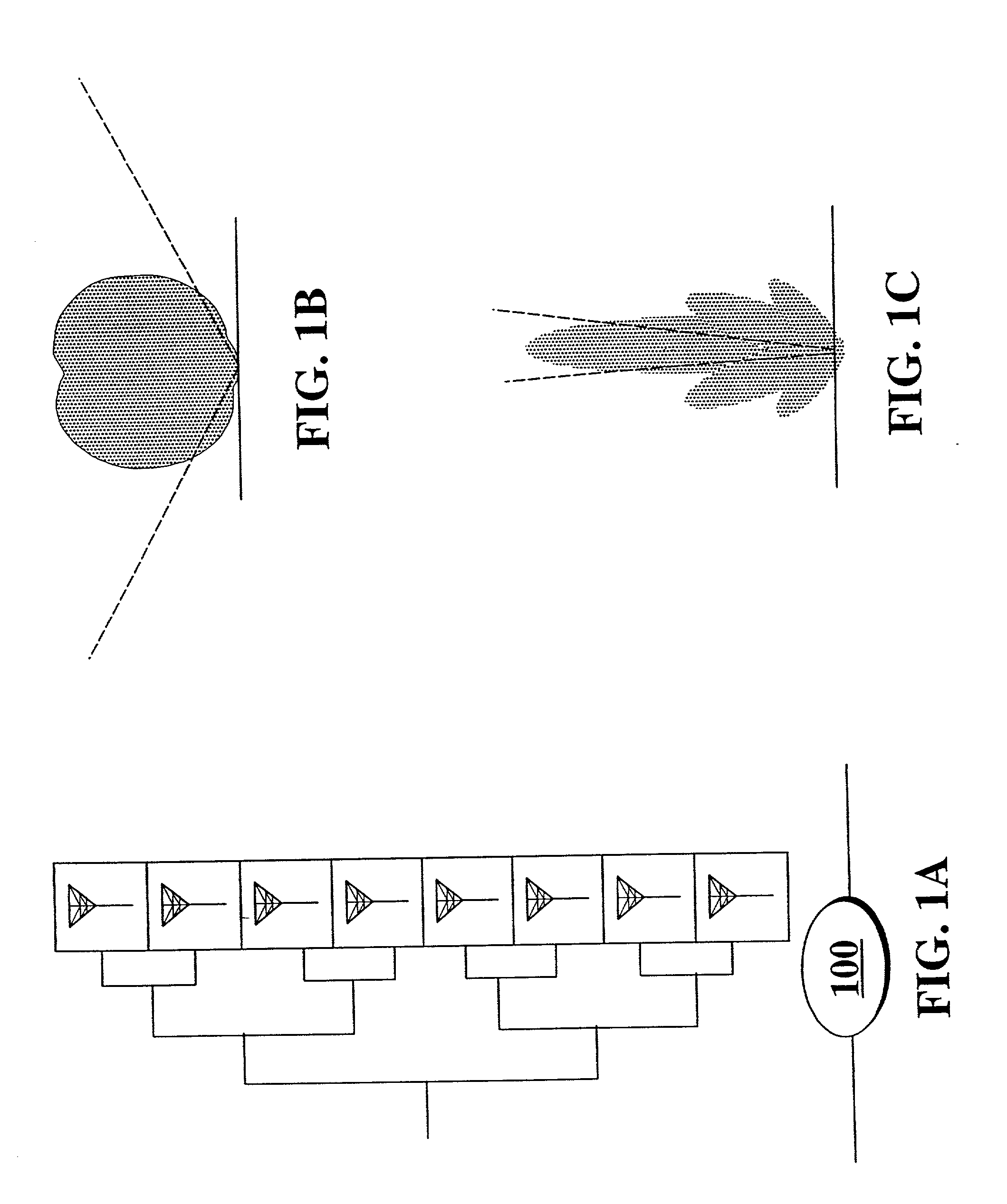
[0050] FIG. 1A depicts a conventional BS antenna array 100, having an 8.times.1 (columnar) arrangement. This antenna arrangement comprises either all transmit or all receive antenna elements. Such an antenna arrangement is capable of radiating highly directional beam patterns in either the elevation or azimuthal plane. Inputs to the array 100 are facilitated by a corporate feed, which. interconnects the antenna elements.

[0051] FIGS. 1B, 1C illustrate different perspectives of a representative radiation beam pattern of a columnar antenna array, such as, antenna array 100, for example. FIG. 1B depicts the radiation beam pattern in the azimuthal plane while FIG. 1C depicts the pattern in the elevation plane. As can be seen from the FIG. 1C, the beam pattern is highly directive in the elevation plane.

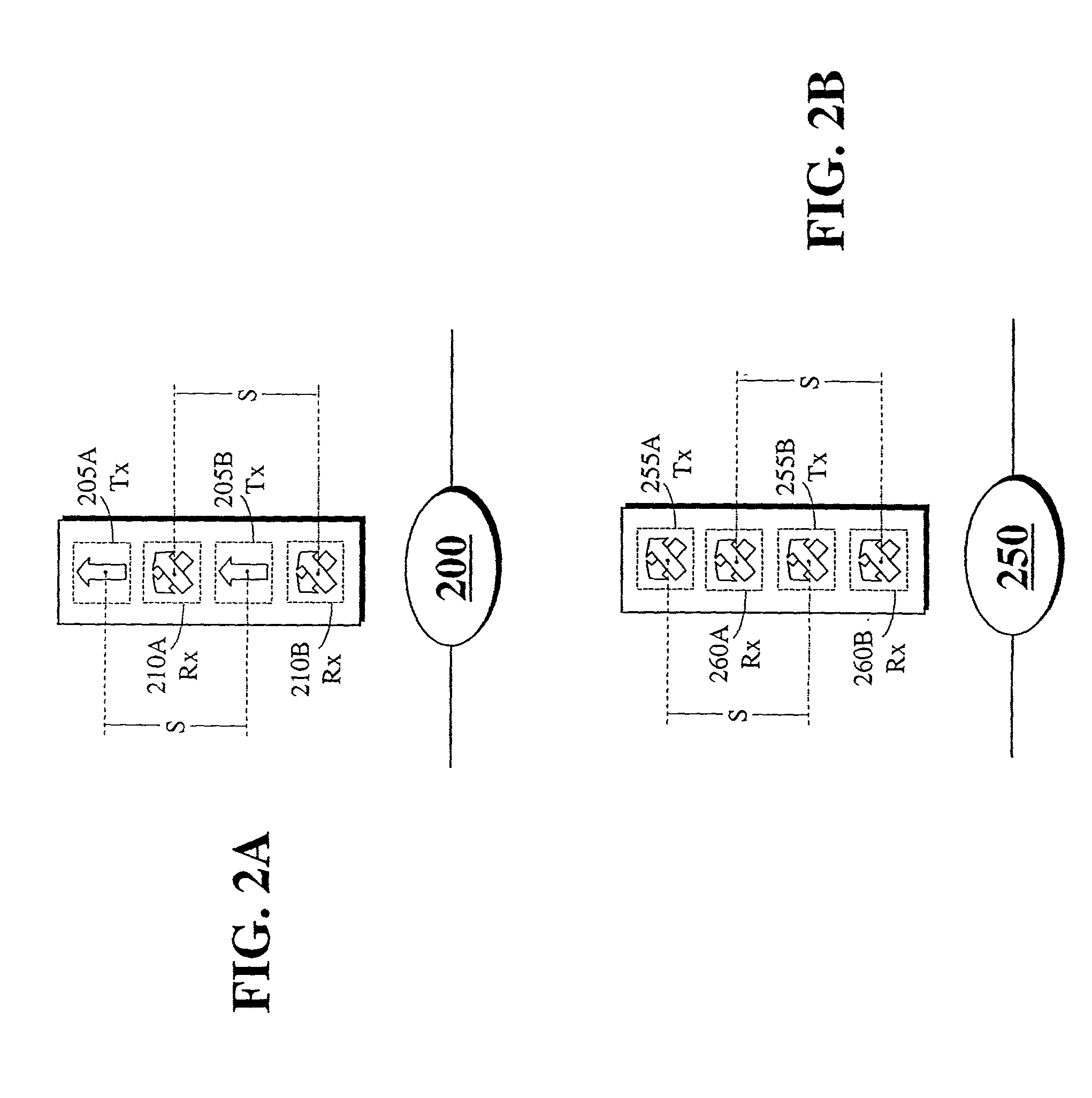
[0052] FIG. 2A illustrates an active antenna array configuration for a BS. As depicted in FIG. 2A, antenna array 200 comprises a combination of 2 active transmit antenna elements 205A, 205B...


PUM


Abstract

Various antenna arrangements are provided with active transmit and receive antenna elements for transmitting and receiving signals within a cellular communication system. Also presented are specific base station antenna systems and methods, and portions thereof, which improve and control specific characteristics and features of antenna systems including antenna beam patterns. In addition, method for the optimization of a cellular communications network is provided which exploits reverse-link, forward-link, and pilot signal information to optimize network operations.

Description

RELATED APPLICATION DATA[0001] The present application is related to the disclosures provided in the U.S. application entitled "Scalable Cellular Communication System" filed (Attorney Docket No. 259817 / 81746) on even date herewith in the names of Joseph Shapira and Gideon Argaman.[0002] This application is a continuation-in-part of the co-pending U.S. application Ser. No. 09 / 171,986, filed Oct. 30, 1998, which was the National Stage of International Application No. PCT / IL98 / 00104, filed Mar. 3, 1998, which claimed the benefit of (and accordingly, this application also claims the benefit of) each of Israeli Application Nos. 120364, filed Mar. 3, 1997, 120706, filed Apr. 20, 1997, and 121201, filed Jun. 30, 1997.[0003] This application is also a continuation-in-part of the co-pending PCT International Application No. PCT / IL98 / 00103, filed Mar. 3, 1998, which claimed the benefit of (and accordingly, this application also claims the benefit of) each of Israeli Application Nos. 120364, f...

Claims


Application Information

Patent Timeline
IPC IPC(8): H01Q1/24H01Q3/26H01Q3/40H01Q21/08H04B1/40H04B7/06H04B7/08H04B7/10H04W88/08
CPCH01Q1/246H01Q3/26H01Q3/2676H01Q3/40H04W88/085H04B1/40H04B7/06H04B7/0848H04B7/10H01Q21/08
Inventor SHAPIRA, JOSEPH
Owner CELLETRA
Why Eureka
Try Eureka