Point to point link and communication method

a point-to-point link and communication method technology, applied in the field of communication networks, can solve the problems of high deployment cost, high cost to the operator, and the backhaul components of conventional base stations require strategic deployment locations on high-end towers, and achieve the effect of improving point-to-point (ptp) communication

Active Publication Date: 2009-09-22
QUALCOMM INC
View PDF12 Cites 97 Cited by
  • Summary
  • Abstract
  • Description
  • Claims
  • Application Information

AI Technical Summary

Benefits of technology

[0015]According to a preferred embodiment, the method and system of the invention involve the use of an antenna array arrangement of multiple omni-directional antennas in each node, one coupled to each modem, each node being able to provide multiple concurrent transmissions over multiple antennas, for example, MIMO (Multiple In Multiple Out) for point-to-point transmissions over a single link, one to three MIMO streams being allocable among the various antennas in the array. Alternatively, a plurality of directional antennas can be utilized, and the number of streams will be defined in accordance with the number and beam width of the antennas. In this way, the present invention provides improved PTP communication having high frequency diversity, variable modulation, turbo or non-turbo coding, preferably using MIMO and dynamically adapted beam forming, according to the instantaneous radio link conditions (such as Signal to Noise Ratio) based on measurements performed over each single link and, when in a network, over a cluster of links (a plurality of nodes).

Problems solved by technology

In conventional systems, the access network and the backhaul network each require their own separate transmission equipment, antennas, etc, at great cost to the operator.
Base station backhaul typically is performed via wired infrastructure (e.g., E1 / T1 leased lines), or via wireless Point-to-point (PTP) microwave links to each base station, which is expensive to deploy (equipment and installation).
In particular, due to the direct, uninterrupted line-of-sight requirements of the wireless backhaul equipment, the backhaul components of conventional base stations require strategic deployment location on high and expensive towers.
This can be achieved by deploying more powerful base station equipment for increasing the cell range (e.g., high power radios, multiple radios on each sector with smart antenna techniques), resulting in more expensive base station equipment.
As the cell coverage area is large, covering a large number of potential subscribers, additional subscribers in each area can rapidly be blocked due to limited base-station capacity.
However, directional antennas are relatively expensive.
Conventional outdoor Wi-Fi access point units require costly power amplifiers in each Wi-Fi AP unit to extend the coverage range.
In addition, conventional Wi-Fi networks operate only on unlicensed bands and suffer from severe interference and difficult radio-planning issues.
Furthermore, in the micro- / pico-cell deployment approach of conventional Wi-Fi-mesh networks, due to multiple access point nodes in the network, backhauling becomes more complicated and costly.
Backhauling each node via wired lines (E1 / T1 or DSL) is impractical in a dense deployment of nodes.
On the other hand, backhauling each node via traditional wireless PTP microwave links is expensive due to costly equipment and installation costs and not feasible to deploy on telephone poles, street poles, electricity poles, etc.
In addition, when the network load is increased, the backhaul network losses drastically degrade the overall network performance (capacity and latency).
Thus, there is no granulation to permit correction of local interference, and, if there is a problem with transmission on one frequency, the entire transmission can be lost due to lack of frequency diversity, so the Signal to Noise Ratio (SNR) of a link (between two base stations) falls on the entire link.

Method used


Image

  • Point to point link and communication method
  • Point to point link and communication method
  • Point to point link and communication method

Examples


Embodiment Construction

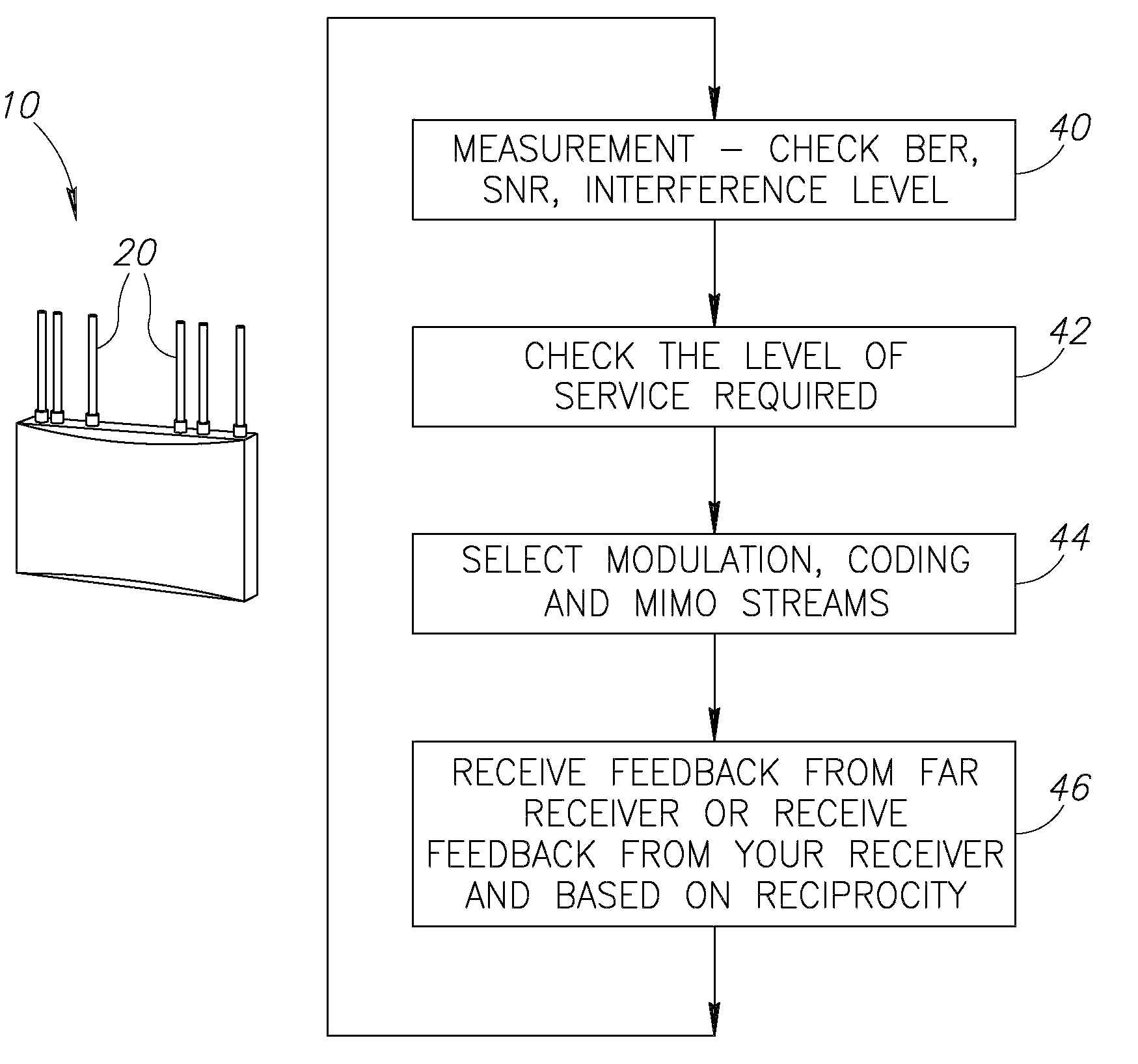
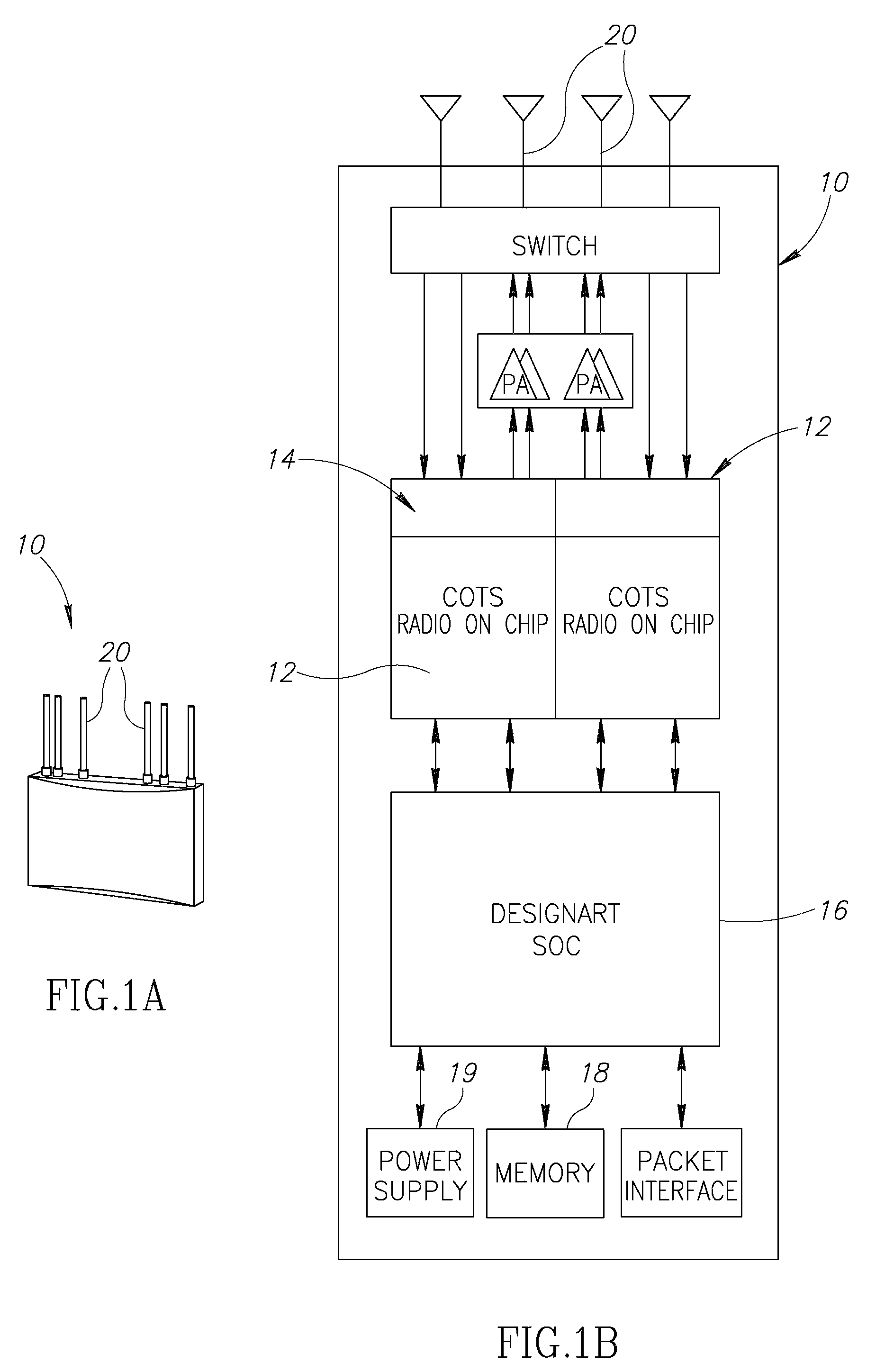
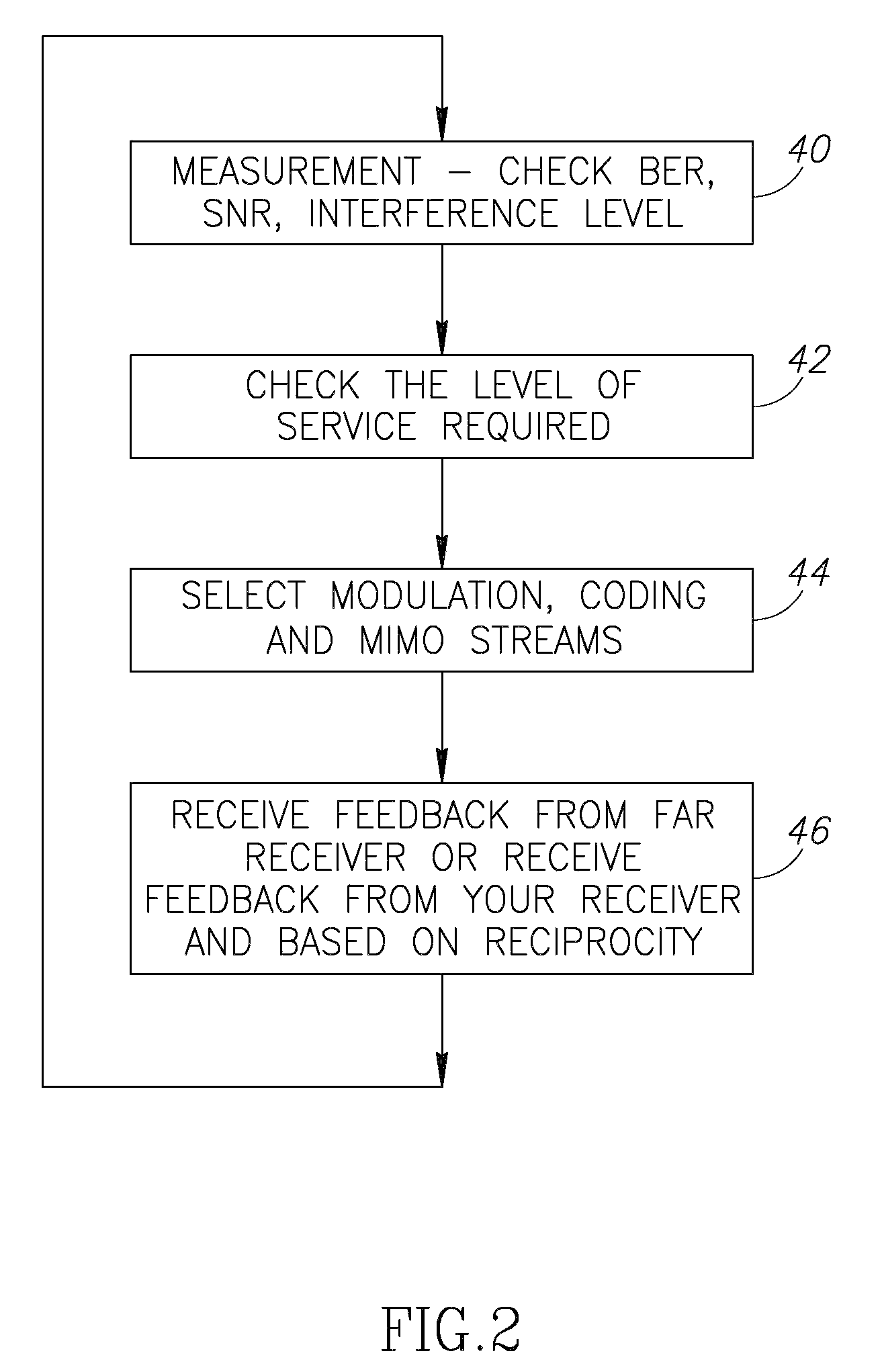
[0030]The present invention relates to a point-to-point communication system between wireless nodes in a wireless network, particularly a next-generation mobile broadband wireless network, serving as an access network or as an internal backhaul network between the various nodes, i.e., base stations, relay stations, access points, etc. For purposes of the present application, all the access and backhauling descriptions refer to any of these possibilities of infrastructure devices. In the discussion that follows, an access network is the air interface network providing communications between access points (base or relay stations) and mobile terminals, for example, as defined by IEEE802.16e—2005 standardization (WiMAX), and a backhaul network is the air interface network providing broadband wireless interconnection between access points within the network (and not traditional backhaul directly from each access point to the core).

[0031]According to one preferred embodiment of the invent...


PUM


Abstract

A method and point-to-point link for providing point-to-point wireless communication between a first and second node forming a link, the method including providing multiple concurrent transmissions from multiple antennas in an antenna array arrangement in the first node, controlling beam patterns of the antennas to manage deployment interference, and periodically allocating 1 to 3 MIMO (Multiple In Multiple Out) streams to different antennas in said antenna arrangement.

Description

[0001]This application claims the benefit of Provisional Applications Nos. 60 / 830,727 and filed 13 Jul. 2006, 60 / 843,079, filed 8 Sep. 2006.FIELD OF THE INVENTION[0002]The present invention relates to communications networks, in general and, in particular, to point-to-point communication in next-generation mobile broadband wireless communication networks as a backhauling system.BACKGROUND OF THE INVENTION[0003]Broadband wireless is expected to be one of the main drivers of the telecommunications industry. There is a substantial increase in demand for broadband connectivity, with personal broadband being the key growth engine for mobile wireless broadband networks.[0004]Communication in such networks is generally divided between access and backhaul. An access network is the air interface network providing traffic communication between mobile terminals (subscribers) and their associated access points (base stations), while a backhaul network is the air interface network providing traf...

Claims


Application Information

Patent Timeline
Patent Type & Authority Patents(United States)
IPC IPC(8): H04W36/00H04B15/00H04M1/00H04W24/00
CPCH04B7/0408H04L1/06H04L1/0003H04L1/0026H04B7/0626H04B7/0669H04B7/0874H04B7/0671
Inventor BARAK, OZTOUBOUL, ASSAF
Owner QUALCOMM INC
Why Eureka
Try Eureka