Power-on circuit of a peripheral component

a technology of power-on circuit and peripheral component, which is applied in the direction of pulse automatic control, electronic switching, pulse technique, etc., can solve the problems of large area of resistor, waste of chip area, and chip area

Inactive Publication Date: 2003-04-24
WINBOND ELECTRONICS CORP
View PDF0 Cites 43 Cited by
  • Summary
  • Abstract
  • Description
  • Claims
  • Application Information

AI Technical Summary

Problems solved by technology

But before the connection is established, due to the existence of filtering and stray capacitors, impulses caused by a power-on current always happen so that a Hub responsible for monitoring the power supply and building a connection protocol will mistake an overloading occurrence of the power supply and disconnect the USB device.
From the viewpoint of designing an IC, the area of a resistor is so large and wastes a chip area.
Therefore, how to efficiently design a circuit that properly builds a connection protocol of the peripheral component and saves a chip area is an important issue.

Method used


Image

  • Power-on circuit of a peripheral component
  • Power-on circuit of a peripheral component
  • Power-on circuit of a peripheral component

Examples


Embodiment Construction

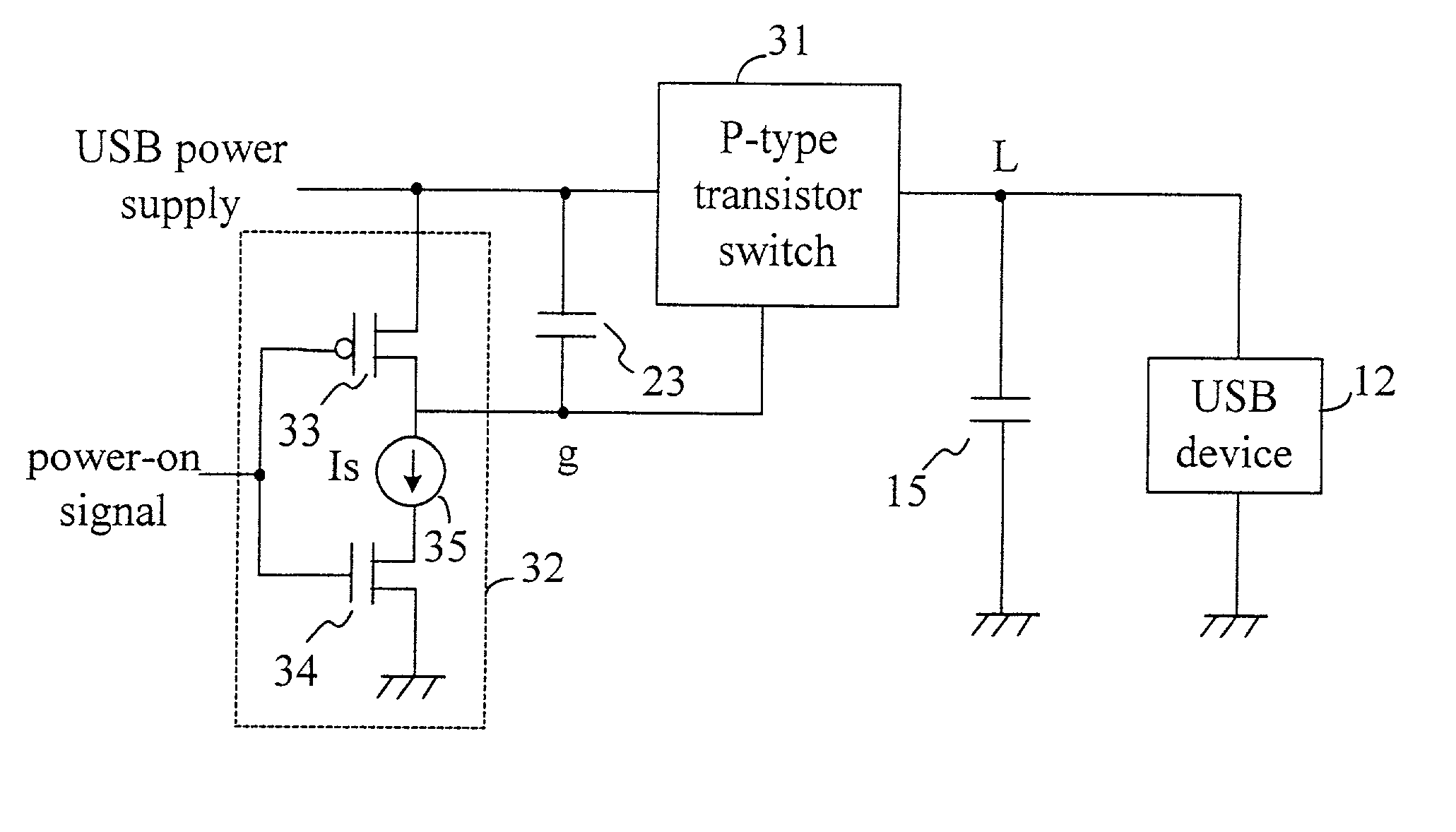
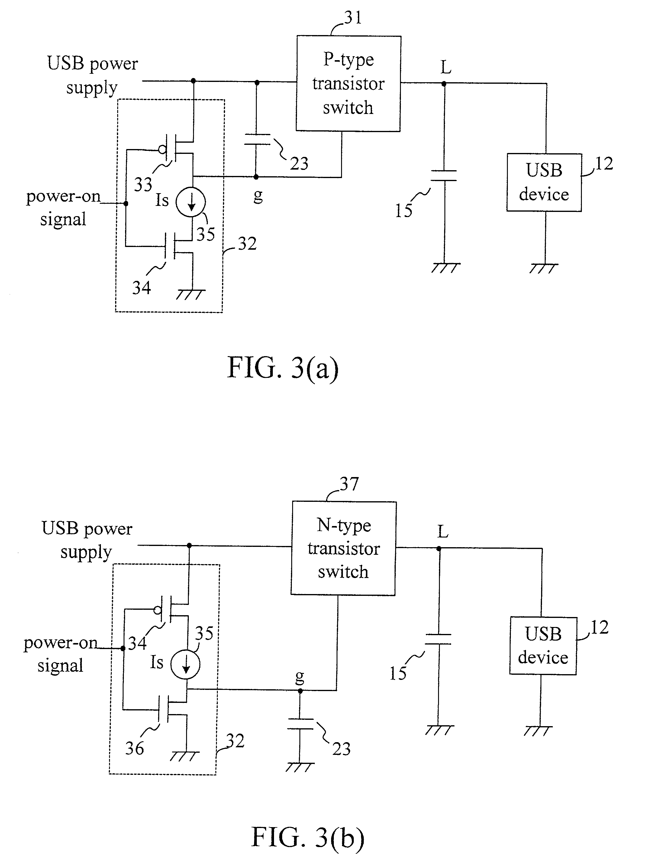
[0017] FIG. 3(a) and 3(b) shows a power-on circuit of the present invention. In FIG. 3(a), a switch control circuit 32 is used to control the enabling time of a P-type transistor switch 31, and using a current source 35 of the switch control circuit 32 to charge a capacitor 23 so as to raise a g-point voltage and obtain the purpose of slowly raising an L-point voltage. The power-on circuit of the present invention comprises a pull-high element (such as a weak P-type transistor) 33, a current source 35 and a current switch (such as a N-type transistor) 34. When the power-on signal has not been turned on, the pull-high element 33 raises the g-point (the gate of the P-type transistor switch 31) voltage V.sub.g into the voltage level of the power supply to avoid erroneously enabling the P-type transistor 31 due to a voltage drop of V.sub.g caused by a leakage current. A current mirror can build the current source 35, and the current from the current source 35 directs to the ground termi...


PUM


Abstract

The present invention discloses a power-on circuit of a peripheral component, which comprises a switch control circuit for controlling the enabling time of a P-type or N-type transistor. For a P-type transistor, the switch control circuit includes a pull-high element, a current source and a current switch. For a N-type transistor, the switch control circuit includes a pull-down element, a current source and a current switch. The enabling time of the P-type or N-type transistors are controlled by the switch control circuit and the capacitor shunt with the switch control circuit so as to slowly enable the transistor switch. In other words, the present invention uses the slowly increasing or decreasing characteristic caused by charging the capacitor with the current source to control the P-type or N-type transistor switch so as to obtain the purpose of slowly enabling the power supply. For designing an IC, it is easy to design a constant current source, which occupies only little area, and the disadvantage of the prior art is thereby resolved.

Description

[0001] 1. Field of the Invention[0002] The present invention relates to a power-on circuit of a peripheral component, particularly to a circuit for reducing instant impulses when the power supply of a peripheral component is turned on.[0003] 2. Description of Related Art[0004] Peripheral components in the modern industries, such as USB (Universal Serial Bus) devices, capture power supply from a USB host. When a USB host is connecting to a USB device, the USB host will provide 100 mA power supply current to the USB device. After the connection is established, the USB device demands the USB host to supply more current. But before the connection is established, due to the existence of filtering and stray capacitors, impulses caused by a power-on current always happen so that a Hub responsible for monitoring the power supply and building a connection protocol will mistake an overloading occurrence of the power supply and disconnect the USB device.[0005] To resolve the above problem, a p...

Claims


Application Information

Patent Timeline
Patent Type & Authority Applications(United States)
IPC IPC(8): G06F1/26H03K17/284
CPCH03K17/284G06F1/26
Inventor HWANG, BAR-CHUNG
Owner WINBOND ELECTRONICS CORP
Why Eureka
Try Eureka