Precision illumination methods and systems

a technology of applied in the field of precision illumination methods and systems, can solve the problems of reducing the number of messages sent to each set of dimmers, requiring special wiring or cabling, and being insufficient for the positioning of mirrors and other mechanical devices

Inactive Publication Date: 2003-05-29
PHILIPS LIGHTING NORTH AMERICA CORPORATION
View PDF71 Cites 387 Cited by
  • Summary
  • Abstract
  • Description
  • Claims
  • Application Information

AI Technical Summary

Benefits of technology

The present invention provides a way to use light therapy to treat medical conditions by selectively targeting specific colors that have been shown to produce beneficial results. This involves creating an LED system capable of emitting all relevant colors within the visible range, choosing which ones will provide maximum benefit based on research into their therapeutic properties, and then shining those chosen colors onto the affected areas of the body for a determined amount of time.

Problems solved by technology

The technical problem addressed in this patent text is the limitations of current lighting networks and the difficulties in controlling electrical devices using standard DMX signals. These networks require special wiring and cabling, and the distance between fixtures is limited. Additionally, conventional methods of controlling electrical devices using pulse width modulated signals have limitations in terms of speed and accuracy. The patent text proposes a new method and system to overcome these drawbacks and take advantage of opportunities provided by overcoming the limitations of conventional lighting networks.

Method used


Image

  • Precision illumination methods and systems
  • Precision illumination methods and systems
  • Precision illumination methods and systems

Examples


Embodiment Construction

[0099] The structure and operation of various methods and systems that are embodiments of the invention will now be described. It should be understood that many other ways of practicing the invention herein are available, and the embodiments described herein are exemplary and not limiting.

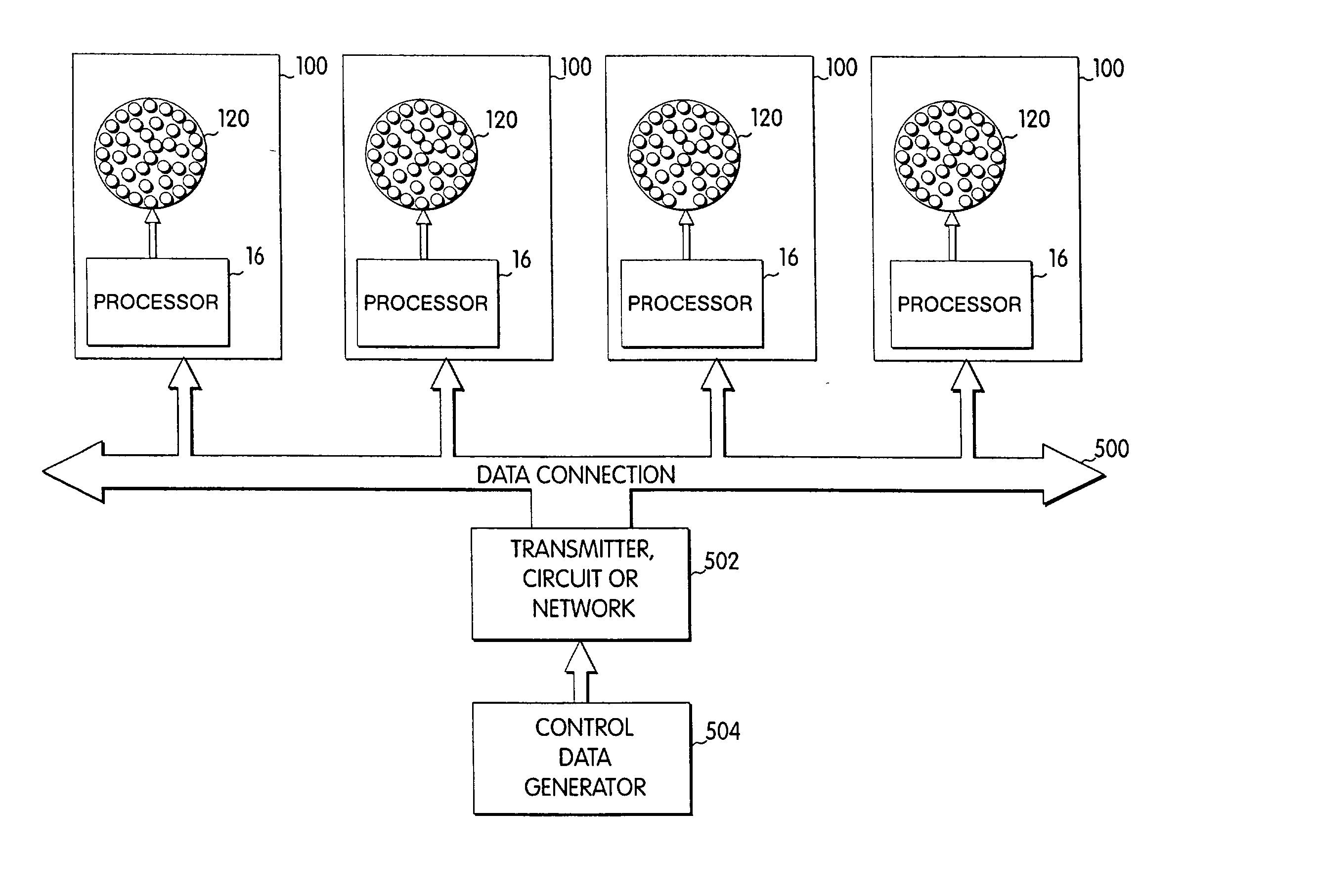
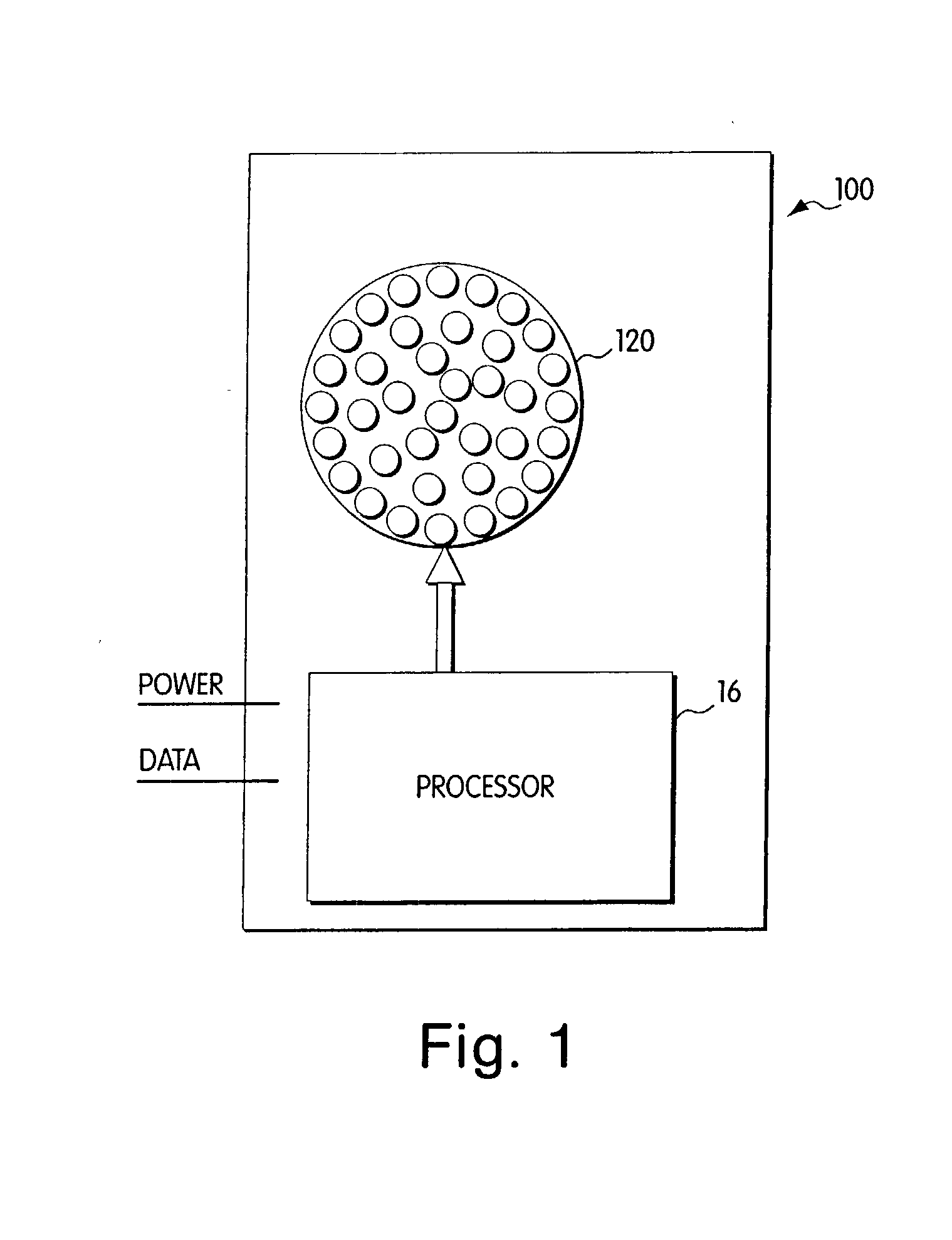
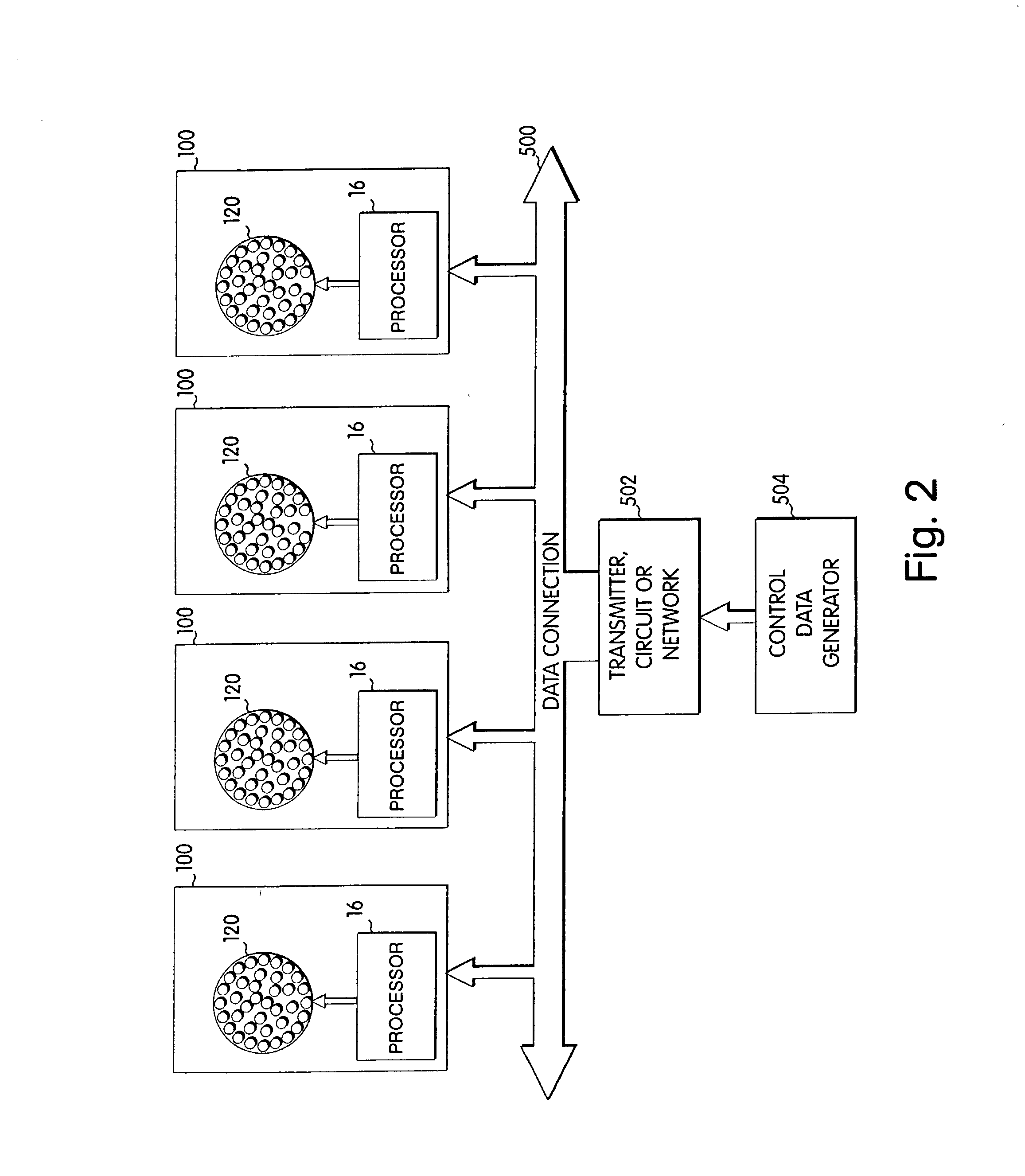
[0100] Referring to FIG. 1, a light module 100 is depicted in block diagram format. The light module 100 includes two components, a processor 16 and an LED system 120, which is depicted in FIG. 1 as an array of light emitting diodes. The term "processor" is used herein to refer to any method or system for processing in response to a signal or data and should be understood to encompass microprocessors, integrated circuits, computer software, computer hardware, electrical circuits, application specific integrated circuits, personal computers, chips, and other devices capable of providing processing functions. The LED system 120 is controlled by the processor 16 to produce controlled illumination. In ...


PUM


Abstract

Methods and systems are provided for illuminating various materials using an LED system. These methods and systems can be applied to a plurality of materials, including biological entities, and may be employed to effect one or more changes in the illuminated material. Exemplary systems may be particularly configured and suitable for use in medical applications, including diagnostic and therapeutic interventions.

Description


Claims


Application Information

Patent Timeline
Owner PHILIPS LIGHTING NORTH AMERICA CORPORATION
Why Eureka
Try Eureka