Combination air separation and steam-generation processes and plants therefore

a technology of air separation and steam generation, which is applied in the direction of machines/engines, lighting and heating apparatus, combustion types, etc., can solve the problems of large amount of unburned coal in the stack, and large number of industrial processes requiring significant electric power consumption

a technology of air separation and steam generation, which is applied in the direction of machines/engines, lighting and heating apparatus, combustion types, etc., can solve the problems of large amount of unburned coal in the stack, and large number of industrial processes requiring significant electric power consumption

US20030101725A1Inactive Publication Date: 2003-06-05LAIR LIQUIDE SA POUR LETUDE & LEXPLOITATION DES PROCEDES GEORGES CLAUDE +1

Image

  • Combination air separation and steam-generation processes and plants therefore
  • Combination air separation and steam-generation processes and plants therefore
  • Combination air separation and steam-generation processes and plants therefore

Examples


embodiment 140

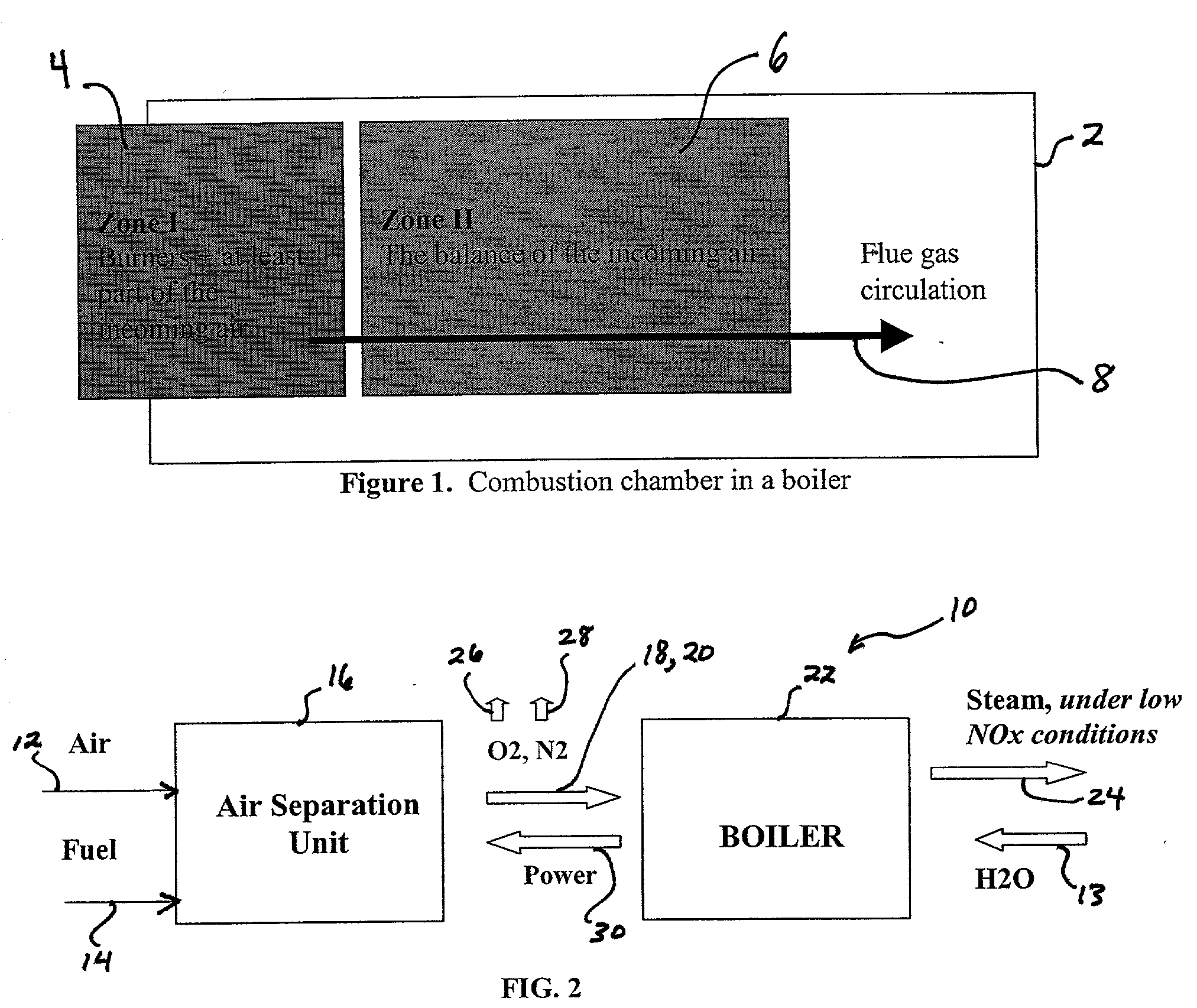
[0069] FIG. 9 presents an alternate embodiment 140, using a cryogenic ASU 16'. In this case, the following streams can be retrieved from the ASU: liquid nitrogen (not shown), liquid oxygen (not shown), liquid argon (not shown), gaseous oxygen at 162 and gaseous nitrogen at 148. The gaseous flow of nitrogen 148, representing the main part of the overall resulting mass (given the ratio between nitrogen and oxygen in the air), is first compressed in compressor 144 to form a compressed nitrogen stream 150 at the desired pressure, after exiting cryogenic ASU 16' at atmospheric pressure (unlike in membranes systems). The compressed nitrogen stream 150 is then preheated to form a preheated gaseous nitrogen stream 152, either inside boiler 22 (see FIG. 9) or outside through heat exchange with flue gases. Finally, the compressed / heated nitrogen flow 152 is sent through a gas turbine 154, which is connected preferably both to the above-mentioned compressor 144 and to a generator 142, where ad...

embodiment 170

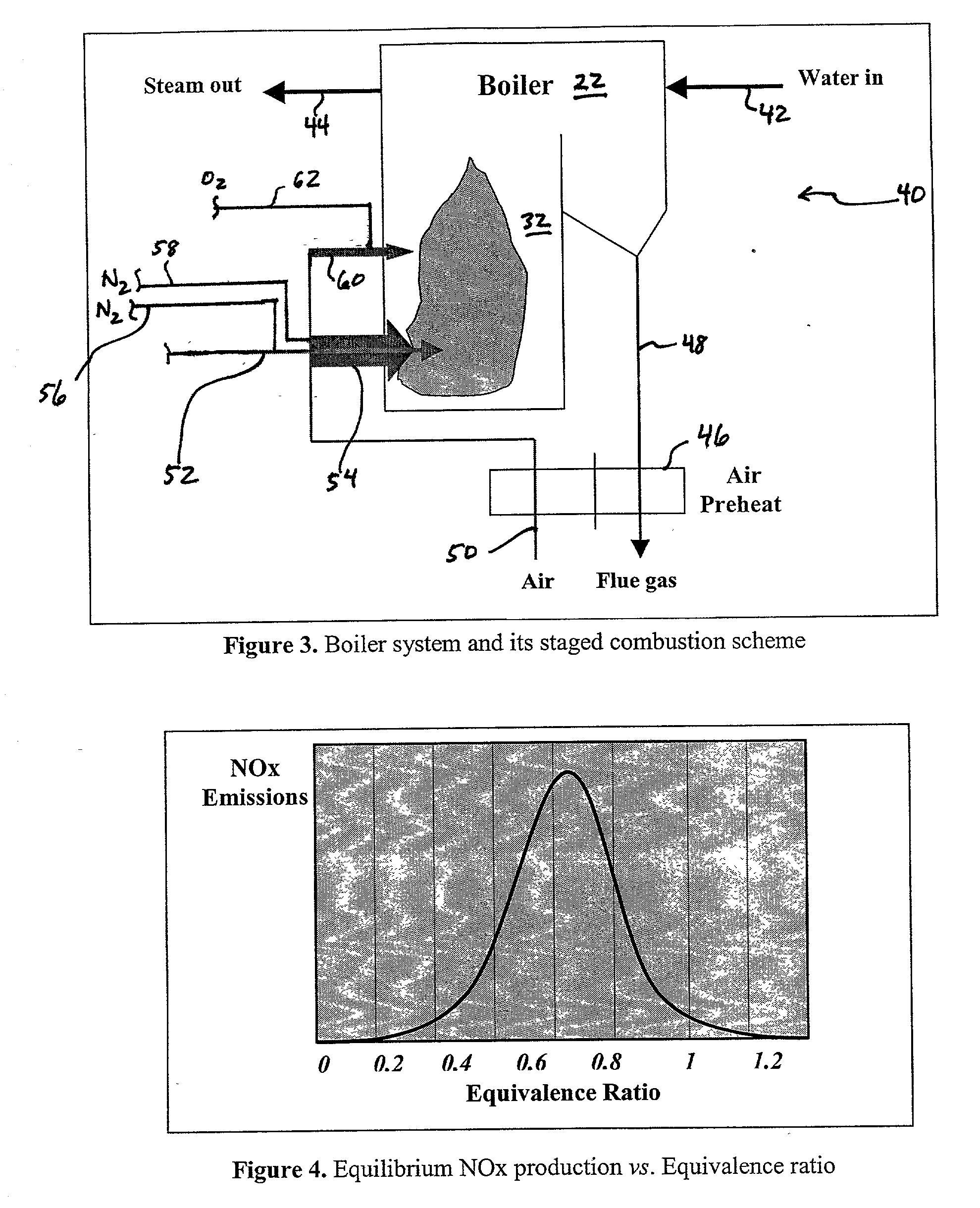
[0072] FIG. 10 describes another embodiment 170 proposed by this invention. The purpose here is to introduce a high velocity stream of oxygen-enriched gas into the second stage of combustion. A membrane ASU 16 is provided, producing a nitrogen-rich stream 124 at Psep, and an oxygen-enriched air stream 96. At least a portion of oxygen-enriched air stream 96 is preferably combined with a preheated air stream 51 produced via heat exchange in air and nitrogen preheated 46'. A combined oxygen-enriched air stream 171 is subsequently routed to a compressor 172 that forms a compressed oxygen-enriched air stream 174, which is fed at high velocity into boiler 22 at the second stage. The velocity of the stream can be subsonic or supersonic, but preferably supersonic: Vox.ltoreq.2 Vs, where Vs is the sonic velocity of the oxidant stream in the conditions of use. Nitrogen-enriched stream 124 is routed to gas turbine 122 and expanded to produce power for air compressor 86, and a low-pressure nitr...


PUM


Abstract

This invention proposes innovative techniques of NOx reduction in boiler operation through an adaptation of staged combustion in combustion boilers. In preferred processes, air is fed into an air separation unit, and a nitrogen-enriched stream is combined with air to produce a nitrogen-enriched first stage air stream, and at least a portion of an oxygen-enriched stream is mixed with air to produce an oxygen-enriched second stage air stream. A reduction in NOx and increase in efficiency is promoted by the inventive processes and systems.

Description

BACKGROUND OF THE INVENTION[0001] 1. Brief Description of the Invention[0002] This invention is related generally to air separation processes, and in particular to air separation processes combined with steam generation facilities.[0003] 2. Related Art[0004] The power generation research and development community faces an important challenge in the years to come: to produce increased amounts of energy under the more and more stringent constraints of increased efficiency and reduced pollution. In order to fulfill both of these goals, it now appears that the power plant of tomorrow will likely have to be modular, and the different modules will likely be combined using advanced system integration techniques.[0005] On the other hand, there are a large number of industrial processes requiring significant electric power consumption. One of these processes is the air separation process, where the power consumption can represent around 50 percent of the overall production costs. The need to...

Claims


Application Information

Patent Timeline
05 Jun 2003
Publication
US20030101725A1
IPC
F23L7/00; F25J3/04
CPC
F23C2201/101; Y02E20/344; F23L2900/07002; F23L2900/07005; F25J3/04018; F25J3/0403; F25J3/04115; F25J3/04145
Inventors
MARIN, OVIDIU; PENFORNIS, ERWIN