
Combination air separation and steam-generation processes and plants therefore

a technology of air separation and steam generation, which is applied in the direction of machines/engines, lighting and heating apparatus, combustion types, etc., can solve the problems of large amount of unburned coal in the stack, and large number of industrial processes requiring significant electric power consumption

Inactive Publication Date: 2003-05-27
LAIR LIQUIDE SA POUR LETUDE & LEXPLOITATION DES PROCEDES GEORGES CLAUDE +1
View PDF38 Cites 40 Cited by
  • Summary
  • Abstract
  • Description
  • Claims
  • Application Information

AI Technical Summary

Benefits of technology

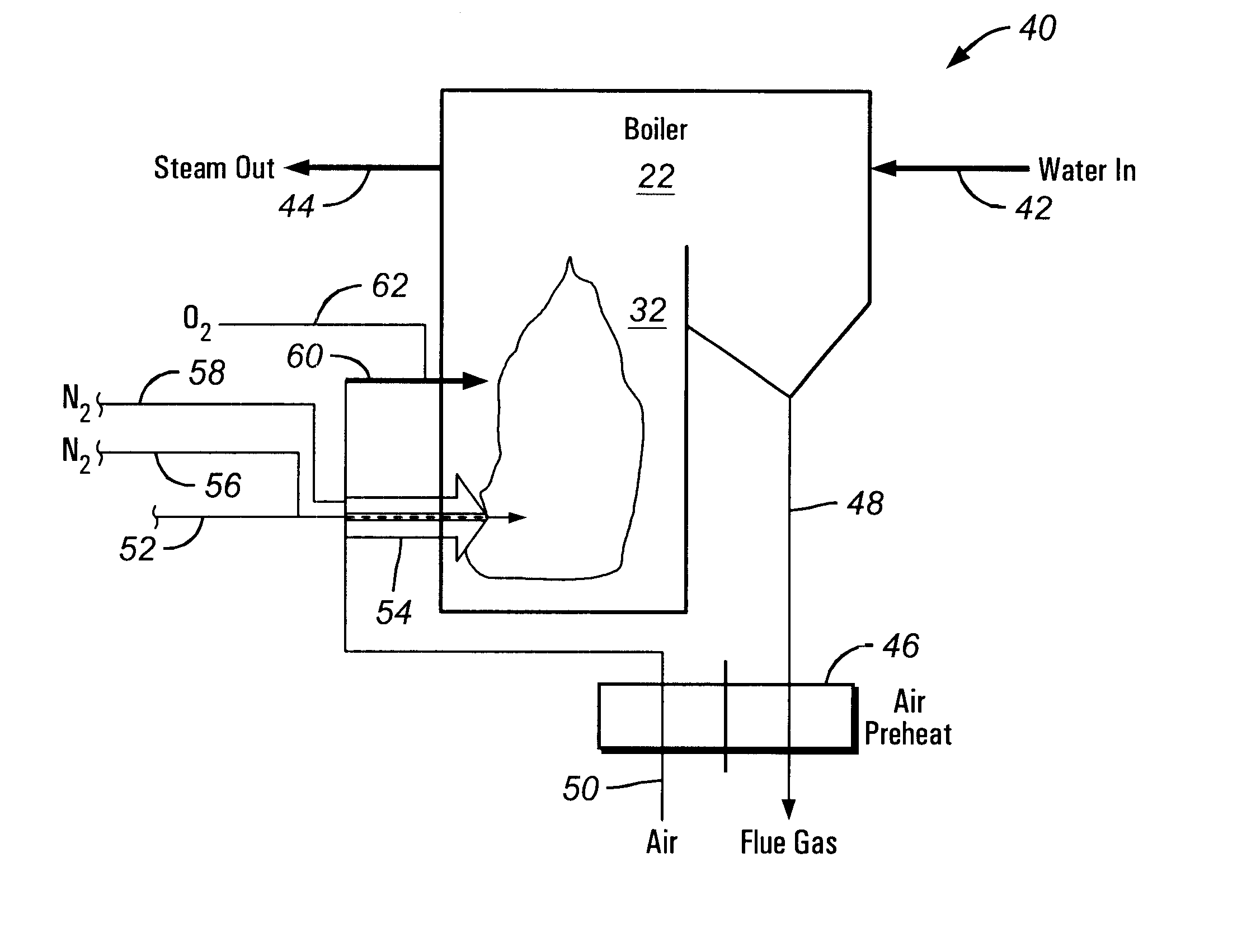
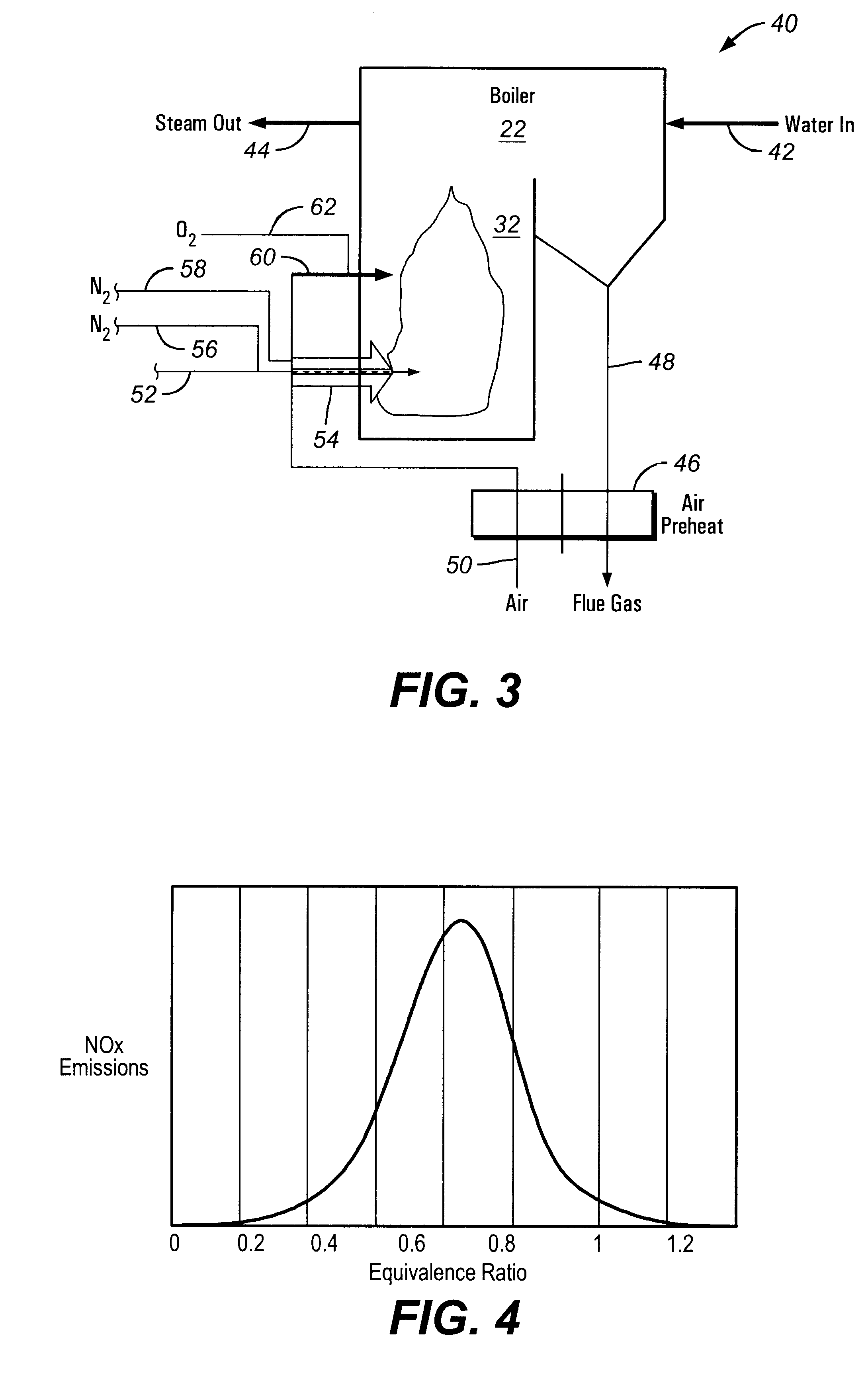
Another advantage of this invention is to combine a low NOx technique with the preservation of the original heat transfer characteristics. This is a very important aspect in boiler operation, since it removes such issues as pipe overheating, due to effects of locally superheating the steam, with negative impact on heat transfer. Theoretically, the use of oxygen-enriched combustion has two consequences to the boiler: it reduces the mass fraction of nitrogen, and it increases the adiabatic temperature of the flame, thus modifying the local heat transfer rates (increase of the radiative transfer and decrease of the convective transfer). In order to preserve the heat transfer patterns the same as for the original air-based case, it should thus be necessary to recirculate a certain mass flow rate of flue gas. This has been the approach in known systems to date.

Problems solved by technology

The power generation research and development community faces an important challenge in the years to come: to produce increased amounts of energy under the more and more stringent constraints of increased efficiency and reduced pollution.
On the other hand, there are a large number of industrial processes requiring significant electric power consumption.
One of these processes is the air separation process, where the power consumption can represent around 50 percent of the overall production costs.
Coal combustion results in a potentially large amount of unburned coal in the stack, thus wasting a large amount of fuel.
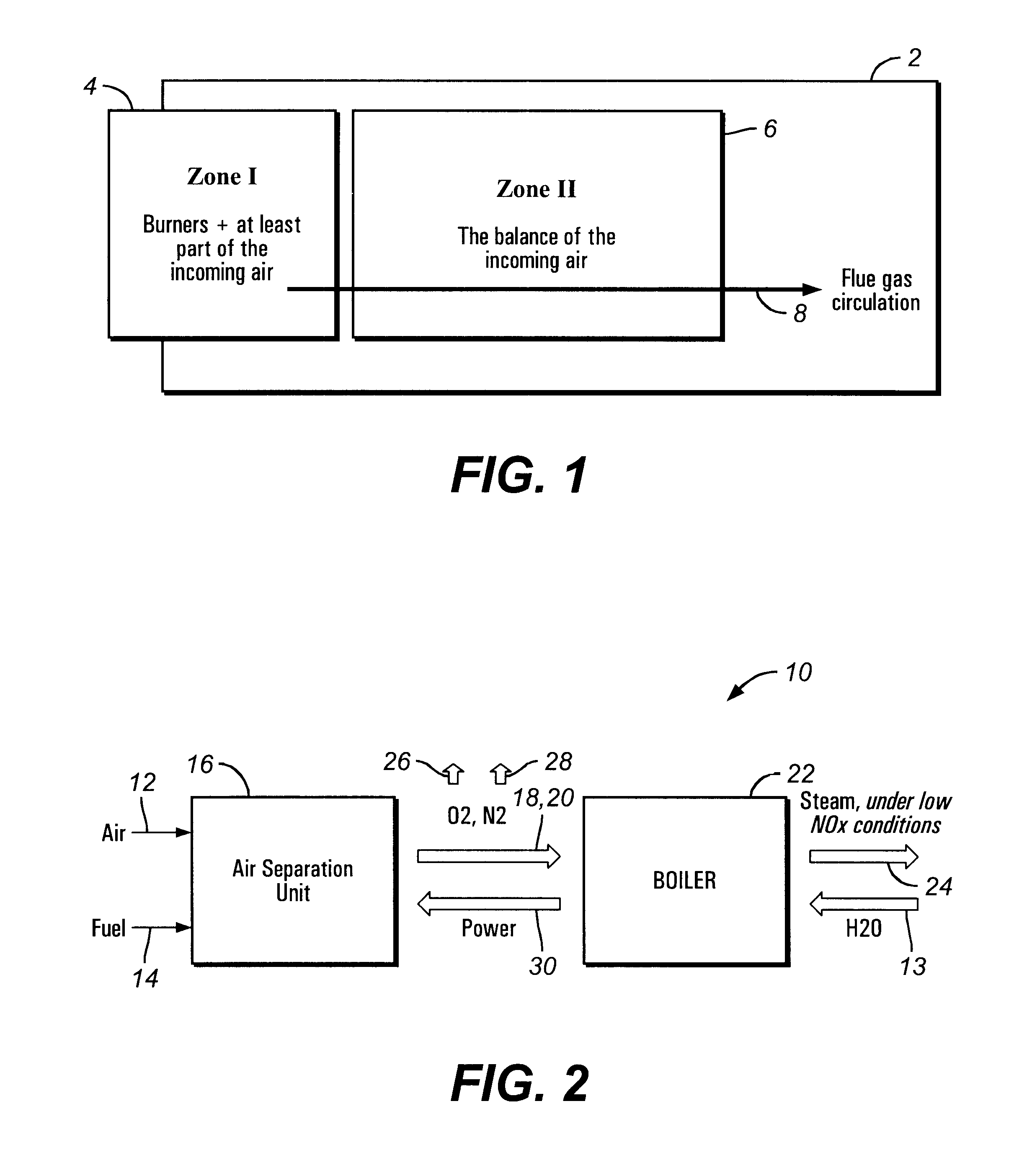
However, due to the low pressure of the incoming air in Zone II, the flow patterns of the main flue gas stream are sometimes relatively undisturbed, thus the mixing between the two streams is relatively poor, preventing the full combustion of the unburned fuel.
However, the very large investment required for a steam generator, together with the already high thermodynamic efficiency of the existing boilers make the introduction of operational changes relatively hard to implement.
The boiler operators are reluctant to introduce modifications in the boiler characteristics, due to possible changes in water vapor properties (temperature, humidity, etc.).
Local vapor superheating may lead to lower heat transfer coefficients, therefore to local pipe overheating, eventually causing cracks in pipes.
Air separation consumes a large amount of electric power, mostly for air compression--just like the gas turbine cycle.
However, no new technological concept can be implemented without thinking in terms of process efficiency and profitability.

Method used


Image

  • Combination air separation and steam-generation processes and plants therefore
  • Combination air separation and steam-generation processes and plants therefore
  • Combination air separation and steam-generation processes and plants therefore

Examples


embodiment 140

FIG. 9 presents an alternate embodiment 140, using a cryogenic ASU 16'. In this case, the following streams can be retrieved from the ASU: liquid nitrogen (not shown), liquid oxygen (not shown), liquid argon (not shown), gaseous oxygen at 162 and gaseous nitrogen at 148. The gaseous flow of nitrogen 148, representing the main part of the overall resulting mass (given the ratio between nitrogen and oxygen in the air), is first compressed in compressor 144 to form a compressed nitrogen stream 150 at the desired pressure, after exiting cryogenic ASU 16' at atmospheric pressure (unlike in membranes systems). The compressed nitrogen stream 150 is then preheated to form a preheated gaseous nitrogen stream 152, either inside boiler 22 (see FIG. 9) or outside through heat exchange with flue gases. Finally, the compressed / heated nitrogen flow 152 is sent through a gas turbine 154, which is connected preferably both to the above-mentioned compressor 144 and to a generator 142, where additiona...

embodiment 170

FIG. 10 describes another embodiment 170 proposed by this invention. The purpose here is to introduce a high velocity stream of oxygen-enriched gas into the second stage of combustion. A membrane ASU 16 is provided, producing a nitrogen-rich stream 124 at Psep, and an oxygen-enriched air stream 96. At least a portion of oxygen-enriched air stream 96 is preferably combined with a preheated air stream 51 produced via heat exchange in air and nitrogen preheated 46'. A combined oxygen-enriched air stream 171 is subsequently routed to a compressor 172 that forms a compressed oxygen-enriched air stream 174, which is fed at high velocity into boiler 22 at the second stage. The velocity of the stream can be subsonic or supersonic, but preferably supersonic: Vox .ltoreq.2Vs, where Vs is the sonic velocity of the oxidant stream in the conditions of use. Nitrogen-enriched stream 124 is routed to gas turbine 122 and expanded to produce power for air compressor 86, and a low-pressure nitrogen st...


PUM


Abstract

This invention proposes innovative techniques of NOx reduction in boiler operation through an adaptation of staged combustion in combustion boilers. In preferred processes, air is fed into an air separation unit, and a nitrogen-enriched stream is combined with air to produce a nitrogen-enriched first stage air stream, and at least a portion of an oxygen-enriched stream is mixed with air to produce an oxygen-enriched second stage air stream. A reduction in NOx and increase in efficiency is promoted by the inventive processes and systems.

Description

BACKGROUND OF THE INVENTION1. Brief Description of the InventionThis invention is related generally to air separation processes, and in particular to air separation processes combined with steam generation facilities.2. Related ArtThe power generation research and development community faces an important challenge in the years to come: to produce increased amounts of energy under the more and more stringent constraints of increased efficiency and reduced pollution. In order to fulfill both of these goals, it now appears that the power plant of tomorrow will likely have to be modular, and the different modules will likely be combined using advanced system integration techniques.On the other hand, there are a large number of industrial processes requiring significant electric power consumption. One of these processes is the air separation process, where the power consumption can represent around 50 percent of the overall production costs. The need to reduce emissions cost-effectively ...

Claims


Application Information

Patent Timeline
Patent Type & Authority Patents(United States)
IPC IPC(8): F25J3/04F23L7/00
CPCF25J3/04018F25J3/0403F25J3/04115F25J3/04145F25J3/04533F25J3/04563F25J3/04581F25J3/04593F25J3/04612F23L7/00F23C2201/101Y02E20/344F23L2900/07002F23L2900/07005F25J2215/50F25J2260/42Y02E20/322Y02E20/34Y02P80/15
Inventor MARIN, OVIDIUPENFORNIS, ERWIN
Owner LAIR LIQUIDE SA POUR LETUDE & LEXPLOITATION DES PROCEDES GEORGES CLAUDE
Learn More