Contact lens

a contact lens and cornea technology, applied in the field of corneal contact lenses, can solve the problems of center bowing out, post-operative problems, and surgery not always successful,

Inactive Publication Date: 2003-06-05
ZELTZER HARRY I
View PDF3 Cites 16 Cited by
  • Summary
  • Abstract
  • Description
  • Claims
  • Application Information

AI Technical Summary

Problems solved by technology

This results in the center bowing out.
However, surgery is not

Method used


Image

  • Contact lens
  • Contact lens

Examples


example 1

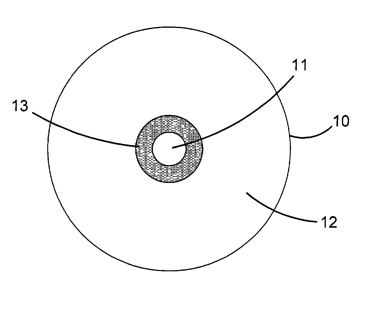
[0017] Referring now to FIG. 1 showing a schematic front view of an eye treated in accordance with this invention, a clear soft corneal contact lens 10 having a diameter of 14.5 mm is coated on its external para center surface with a light blocking ring 13 of black dye. The 2 mm center 11 remains clear and has the correct lens power to allow for a very sharp retinal image in daylight. The width of the black ring 13 surrounding the clear center is 1 mm to provide an apparent pupil size of 4 mm. when inserted onto the cornea. The remaining 5.25 mm. portion 12 of the lens is clear.

example 2

[0018] Referring now to FIG. 2 showing a schematic front view of an eye treated in accordance with this invention, a clear soft corneal contact lens 20 having a diameter of 14.5 mm. is coated on its external para center surface with a 4.5 mm. wide light blocking ring 15 of a selected color and has a 3 mm. wide clear central pupil 14. The remaining outer 1.25 mm. wide ring 16 is clear.

EXAMPLES OF HOW THE INVENTION HELPS EYE PROBLEMS

example 3

[0019] A patient with bilateral corneal irregularity and best corrected visual acuity of 20 / 40 in each eye with soft contact lenses, would if fitted with a pupil reduction lens made in accordance with the specifications below and using the same soft lens material and prescription, have an increase in visual acuity in each eye to 20 / 25.

[0020] Specifications:

[0021] O.U. -1.50 Diopters, Radii 8.30 mm., diameter 13.8 mm., thickness 0.19 mm., clear pupil diameter 2 mm., black pupil ring (1 mm.), remainder of lens clear.


PUM


Abstract

A pupil reduction corneal contact lens having a light-admitting central area surrounded by a light-blocking area. The central area can be clear or have a slight tint for reducing glare that would not reduce visual acuity to 20/25 or less. The lenses can be soft, gas-permeable or hard.

Description

CROSS-REFERENCE[0001] The Applicant hereby invokes the benefits of 35 U.S.C. 119(e)(1) with respect to the invention disclosed by the Applicant in pending provisional application S. No. 60 / 334,961 filed Dec. 4, 2001.BACKGROUND OF INVENTION[0002] This invention relates to a novel corneal contact lens which corrects refractive errors but also reduces aberrations, thus improving visual acuity to the highest possible level for contact lens correction.[0003] There are many aberrations of the cornea. The larger the pupil the greater the aberrations.[0004] 1. Spherical aberrations are caused by a gradual flattening of its peripheral curvature. Therefore, light has variable foci which smear the image and reduce contrast.[0005] 2. Coma aberration occurs where light that enters the pupil off the visual axis (at an angle) will appear as a fuzzy circle. The farther it is off the axis as through a larger pupil, the larger is the circle. The circle takes on a comet-like image thus reducing visual...

Claims


Application Information

Patent Timeline
IPC IPC(8): G02C7/04
CPCG02C7/16G02C7/104
Inventor ZELTZER, HARRY I.
Owner ZELTZER HARRY I
Why Eureka
Try Eureka