
Welding method and welding system for projection bolt

Inactive Publication Date: 2003-07-10
AOYAMA YOSHITAKA
View PDF0 Cites 5 Cited by
  • Summary
  • Abstract
  • Description
  • Claims
  • Application Information

AI Technical Summary

Benefits of technology

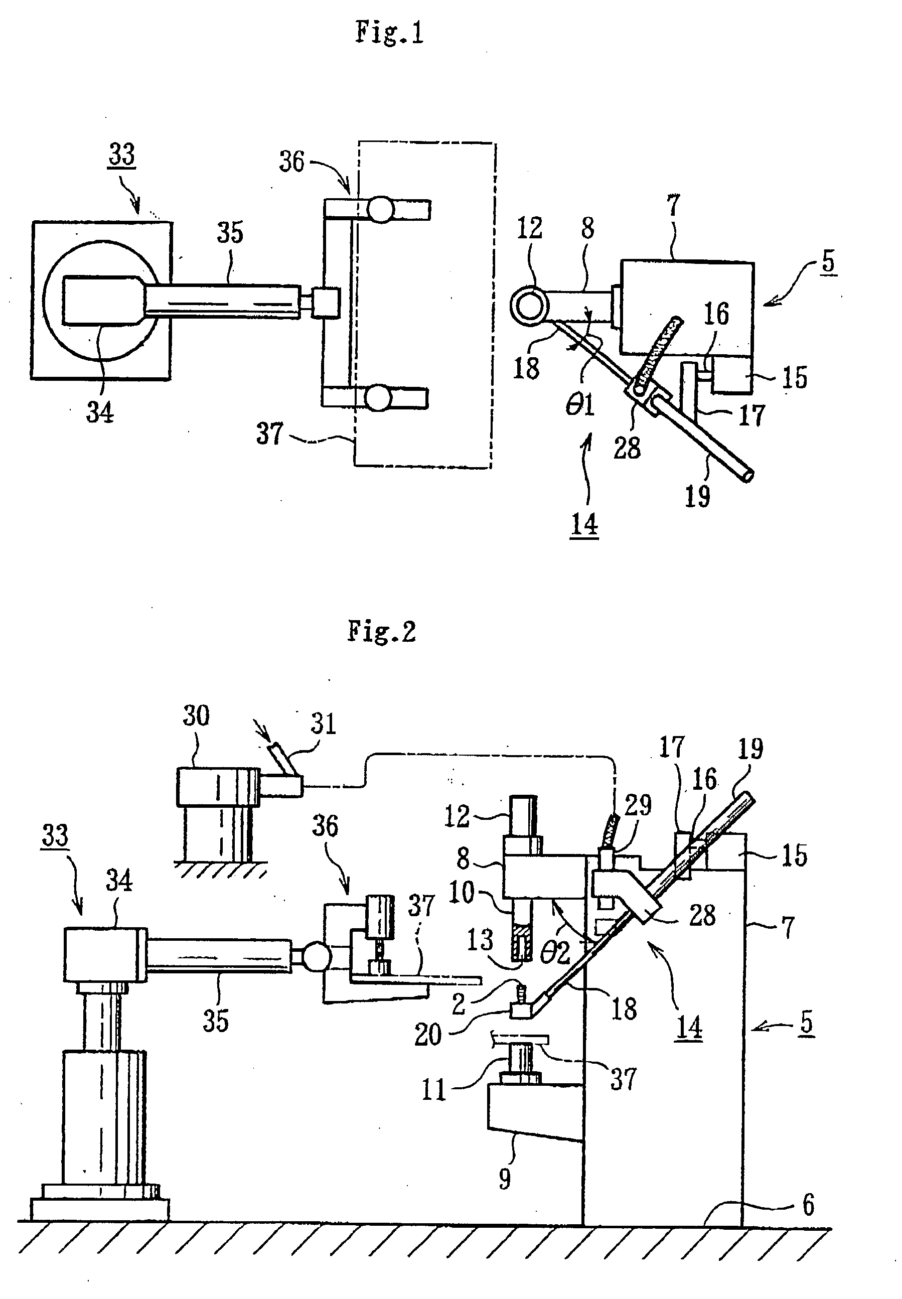
[0014] The feed rod is provided on a projection bolt feed apparatus, which can be mounted on part of the welding machine. Since the projection bolt feed apparatus is to be mounted on an existing welding machine as an additional component, a minor modification of the welding machine enables the installation of the feed apparatus on the welding machine. Therefore, it is also advantageous in terms of equipment arrangement and economy.
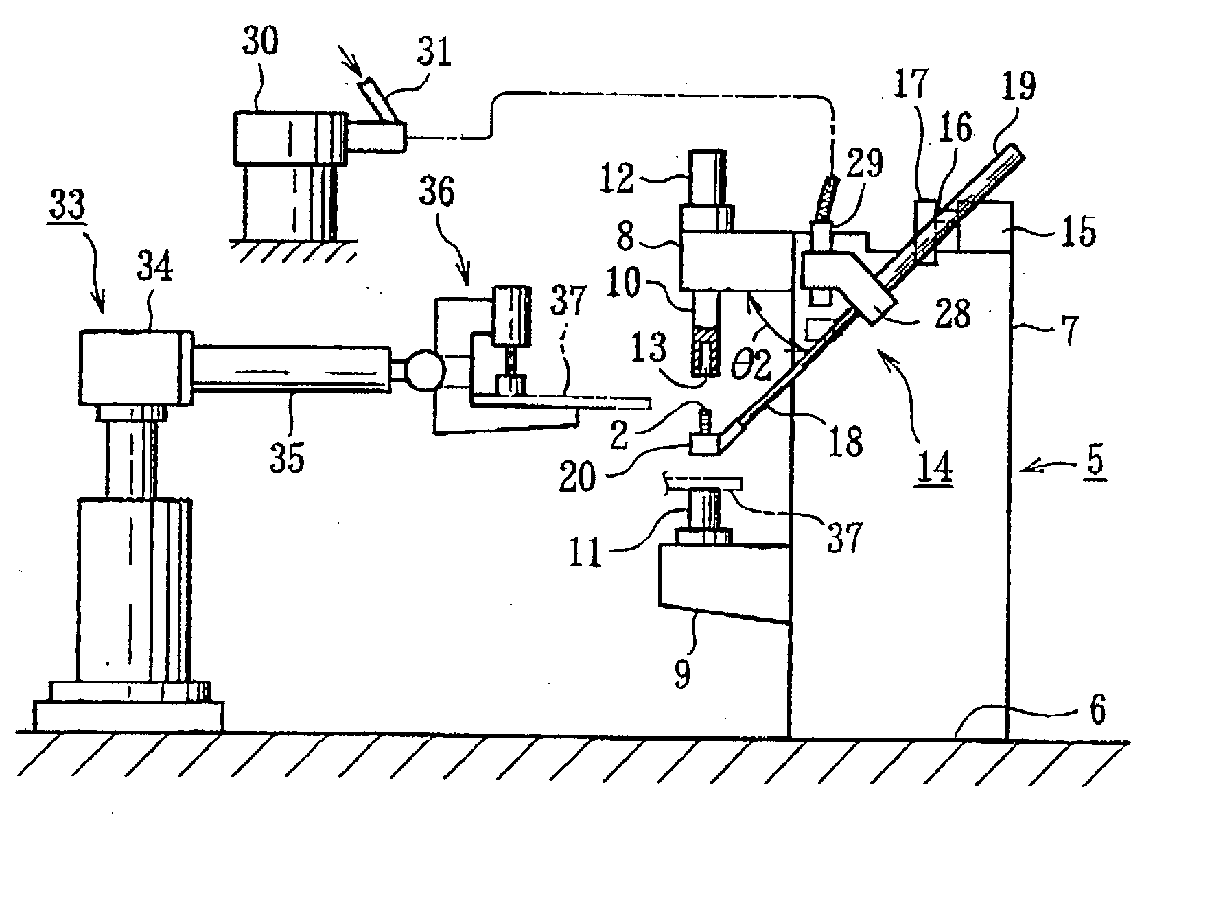
[0015] It is desirable that the projection bolt feed apparatus be arranged on the rear of the electrodes in the view across the length of the supporting arms. This arrangement prevents the projection bolt from interfering with a work when it comes into between the movable electrode and the fixed electrode. Both electrodes are arranged on the extremity of the supporting arms, respectively, so that the work is guided to a position between both the electrodes first, and is subjected to a welding operation smoothly without interfering with other members.
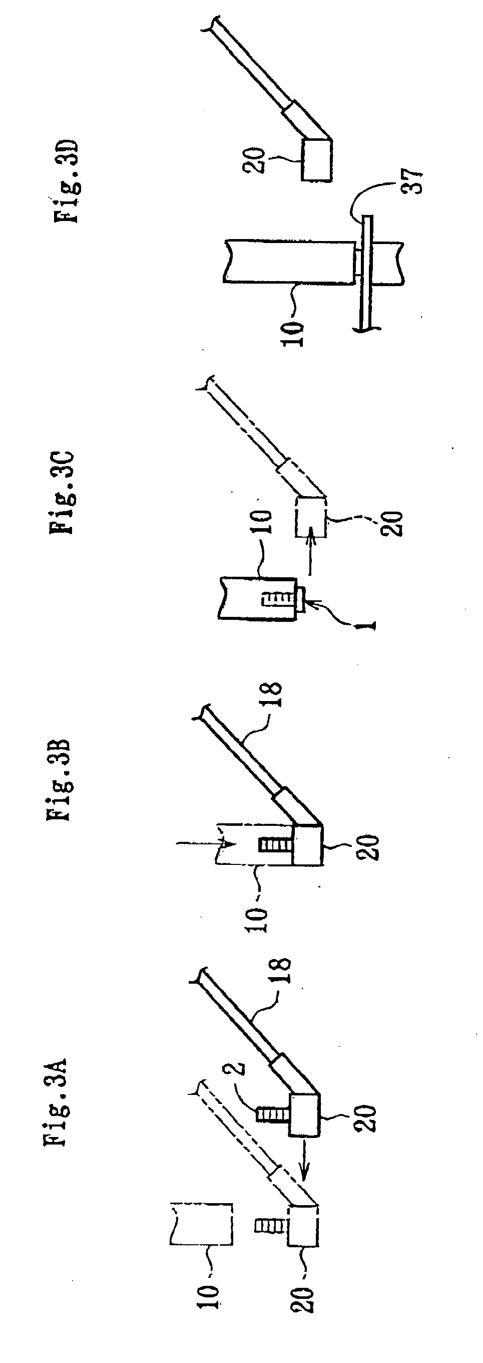
[0016] It is also desirable that a drive means for retreating the holding head from the axis of the movable electrode for moving back and forth be provided. When the movable electrode is moved forward and the shank of the bolt is inserted in the receiving hole in a prescribed length, the electrode stops moving at that point. Then, the holding head is retreated from the axis of the movable electrode for moving back and forth by the drive means. As described here, while the forward movement of the movable electrode is under accurate control, it is stopped and the holding head is retreated, so that the holding head is retreated after the bolt has been held surely in the receiving hole of the movable electrode. Therefore, the operation of moving forward the movable electrode and retreating the holding head is precisely carried out, which provides a highly reliable operability.

Problems solved by technology

The insertion length for the shank, however, is not accurately controlled in the prior art.
As a result, such a case may occur that an inserting rod resets at a stage at which the insertion length is insufficient, or that the projection bolt is inserted excessively enough to make a member holding the bolt interfere with the extremity of the electrode.
The former case causes the bolt to come off from the receiving hole, due to the insufficient insertion of the bolt, and the latter case results in damaging the extremity of the electrode or the bolt holding member.
These problems occur because the rod for bolt insertion is driven by fluid pressure supplied by an air cylinder and the like.
The prior art, however, lacks a particular consideration for improving the productivity of welding processes.
Further, the prior art does not meet satisfactorily a demand that existing equipment is modified in the least extent to achieve the simplification of the equipment and reduction of an equipment cost.
Meanwhile, in the prior art, the shank of the bolt cannot be inserted in the receiving hole of the electrode while the work is kept arranged between both electrodes.
That is, the shank insertion with an insufficient length makes the shank incline abnormally in the receiving hole when the holding head retreats in the direction perpendicular to the electrode axis, making it difficult to insert the shank into the receiving hole smoothly.
On the other hand, if the movable electrode is allowed to move forward to come too close to the holding head, the holding head and the movable electrode come to interfere, damaging each other.
If the forward movement of the movable electrode is controlled by a conventional technique, such as an air cylinder, it will be extremely difficult to temporarily stop the electrode within a required range and allow it to move forward again.

Method used


Image

  • Welding method and welding system for projection bolt
  • Welding method and welding system for projection bolt
  • Welding method and welding system for projection bolt

Examples


Embodiment Construction

[0039] First, a projection bolt is described referring to FIG. 11. The projection bolt 1 is, for example, made of steel, having a shank 2, a circular flange 3 integrally formed with the shank 2, and a welding projection 4 formed on the surface of the flange opposite to the shank side. It is applicable to the embodiment to form a plurality of, for example three or four of, wart-shaped projections, instead of forming a welding projection with the illustrated shape.

[0040] In FIGS. 1 and 2, a stationary welding machine, shown as a general view, is represented by a reference number 5, wherein supporting arms 8, 9 are joined to a pillar 7 erected on a floor 6. The supporting arms 8, 9 have a movable electrode 10 and a fixed electrode 11, respectively, wherein the movable electrode 10 is driven with a motor 12 mounted on the supporting arm 8. Either of the electrode 10 or electrode 11 is provided with a receiving hole 13 for receiving the shank 2 of the projection bolt 1. It is clearly sho...


PUM

PropertyMeasurementUnit
Lengthaaaaaaaaaa

Abstract

A welding method and a welding system for a projection bolt are provided. The disclosure comprises a stationary welding machine (5) having supporting arms (8, 9), each of which is provided with a movable electrode (10) and a fixed electrode (11) and either of the electrodes has a receiving hole (13) formed thereon for receiving the shank (2) of the projection bolt (1), wherein a projection bolt feed apparatus (14) is mounted on the stationary welding machine (5). According to the disclosure, the projection bolt (1) is stopped in the position where the shank (2) of the bolt (1) is coaxial with the receiving hole (13), then, the shank (2) is inserted into the receiving hole (13). A robot apparatus (33) brings a work (37) in between both the electrodes, where the welding operation of welding the projection bolt (1) to the work (37) is completed.

Description

[0001] This application is a continuation application of a PCT application serial No. PCT / JP01 / 05560 filed on Jun. 28, 2001. All of the disclosures are incorporated herein by reference.[0002] 1. Field of the Invention[0003] This invention relates in general to a welding method and a welding system for a projection bolt.[0004] 2. Description of Related Art[0005] A projection bolt comprises a shank on which screw threads are formed, a flange formed on one end of the shank, and a welding projection formed on the surface of the flange opposite to the shank side, wherein the welding projection is melted to be welded to a plate-shape work. The Japanese Patent No. 2509103 discloses an invention, in which a projection bolt, whose shank is inserted in a receiving hole formed on a movable electrode, is welded to a work, such as a steel plate and the like, when the movable electrode moves forward. The projection bolt is stopped first on the axis of the movable electrode, then is moved along th...

Claims


Application Information

Patent Timeline
IPC IPC(8): B23K9/20B23K11/14
CPCB23K11/14B23K9/206
Inventor AOYAMA, YOSHITAKAAOYAMA, SHOJI
Owner AOYAMA YOSHITAKA
Learn More