Golf club head with a carbon fiber block

a golf club head and carbon fiber technology, applied in the field of golf club heads, can solve the problem of limited face area (42) of the golf club head (40)

Inactive Publication Date: 2003-07-24
ADVANCED INT MULTITECH CO LTD
View PDF2 Cites 202 Cited by
  • Summary
  • Abstract
  • Description
  • Claims
  • Application Information

AI Technical Summary

Problems solved by technology

However, because the conventional iron head (40) is always made of metal and the weight of the

Method used


Image

  • Golf club head with a carbon fiber block
  • Golf club head with a carbon fiber block
  • Golf club head with a carbon fiber block

Examples


Embodiment Construction

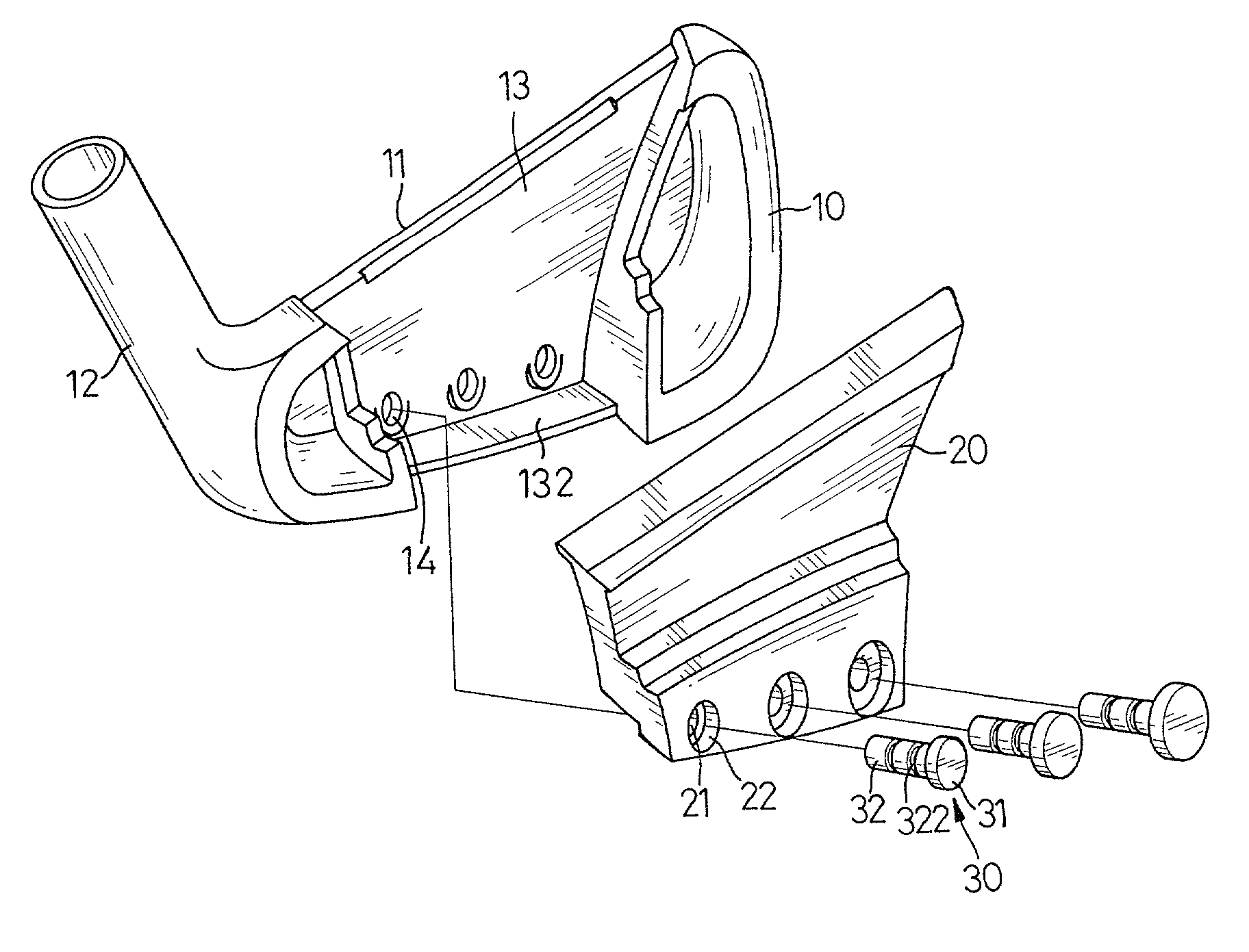
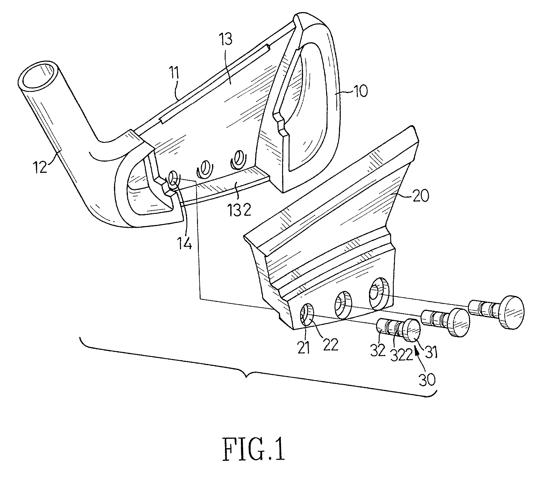
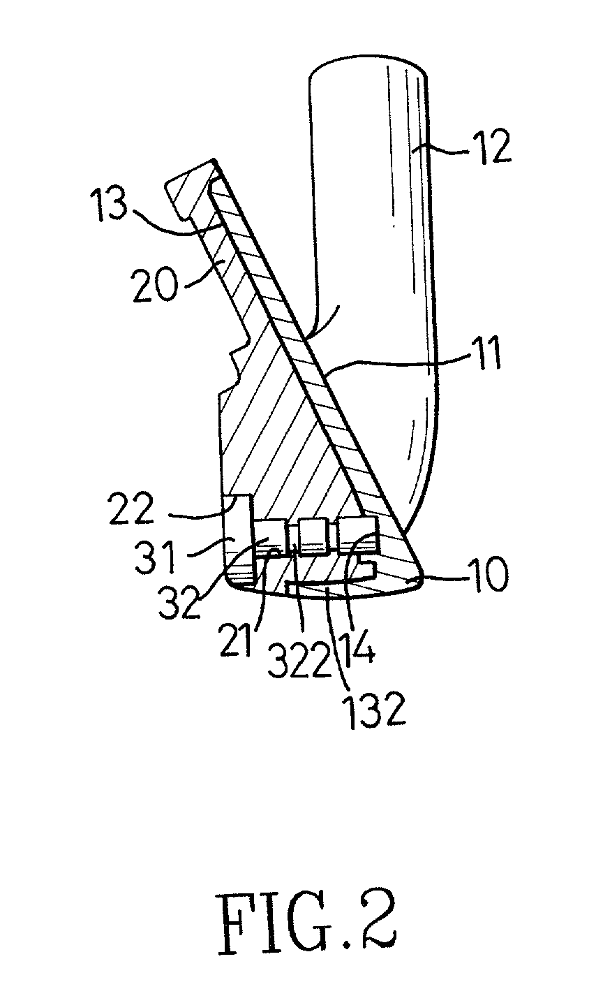
[0012] With reference to FIG. 1, a golf club head in accordance with the present invention comprises a body (10) and a carbon fiber block (20). The body (10) has a face (11) defined on one side of the body (10) for hitting the golf ball. A tubular neck (12) is integrally formed on one end of the body (10) to connect with a shaft of an iron. A cavity (13) is defined in the body (10) opposite to the face (11).

[0013] The carbon fiber block (20) is securely mounted in the cavity (13). A lip (132) laterally extends from the face defining the cavity (13) of the body (10) to engage the block (20), such that the attachment between the body (10) and the block (20) is enhanced.

[0014] At least one countersunk through hole (21) is defined in the block (20). A weighted plug (30) is-inlaid in each-countersunk through hole (21) in the block (20). Each weighted plug (30) has a head (31) and a shaft (32). The plug (30) shaft (32) integrally extends from the head (31). The head (31) has a diameter la...


PUM


Abstract

A golf club head has a body and a carbon filter block. The body has a face defined on one side of the body. A tubular neck is integrally formed on one end of the body. A cavity is defined in the body opposite to the face. The carbon fiber block is mounted in the cavity. Because the carbon fiber material is lighter than metal, the area of the face is enlarged. In addition, a better shock absorbing effect is achieved due to the arrangement of the carbon fiber block.

Description

[0001] 1. Field of the Invention[0002] The present invention relates to a golf club head, and more particularly to a golf club head with a carbon fiber block, such that the face of the golf club head can be enlarged.[0003] 2. Description of Related Art[0004] With reference to FIG. 4, a conventional golf club head (40) for an iron comprises a body (41) and a tubular neck (43). A face (42) is defined in one side of the body (41) for hitting the golf ball. The neck (43) is integrally formed on one end of the body (41) to connect with a shaft of a golf club. In general, the golf club head (40) is usually manufactured in one of two ways, one is to cast the head (40) with a mold, and the other is forge the head from a single block of metal. However, because the conventional iron head (40) is always made of metal and the weight of the golf club head is standardized, the area of the face (42) of the golf club head (40) is limited. A new golfer easily misses the golf ball with an iron having...

Claims


Application Information

Patent Timeline
IPC IPC(8): A63B53/04A63B53/06A63B102/32
CPCA63B53/04A63B2053/0416A63B53/047A63B2209/02A63B2053/0433A63B2053/0491A63B53/0416A63B53/0433A63B60/00
Inventor CHENG, BERNARDCHEN, HSIAO-KUNCHIU, JEN-HUNG
Owner ADVANCED INT MULTITECH CO LTD
Why Eureka
Try Eureka