Removable large wheel assembly for luggage with small wheels

a large wheel and luggage technology, applied in the direction of folding cycles, cycles, car/perambulator with multiple axes, etc., can solve the problems of unstable front and back wheels, easy overturning, and reduce the assembly to two removable parts, namely, the two large wheels, and achieve easy assembly and disassembly, and low cost. , the effect of fewer components

Inactive Publication Date: 2003-07-31
EDWARDS ANTHONY G
View PDF0 Cites 8 Cited by
  • Summary
  • Abstract
  • Description
  • Claims
  • Application Information

AI Technical Summary

Benefits of technology

0012] A still further object of the invention is to provide a large wheel assembly which has relatively few component parts and can be easily assembled and disassembled.
0013] A yet further object of the invention is to provide a large wheel assembly which is relatively inexpensive to manufacture and assemble.

Problems solved by technology

Such larger luggage, even with a front set of wheels and a back set of wheels can be unstable and can be easily overturned when being pushed or pulled in their transport.
This method reduces the assembly to two removable parts, namely, the two large wheels.

Method used


Image

  • Removable large wheel assembly for luggage with small wheels
  • Removable large wheel assembly for luggage with small wheels
  • Removable large wheel assembly for luggage with small wheels

Examples


Embodiment Construction

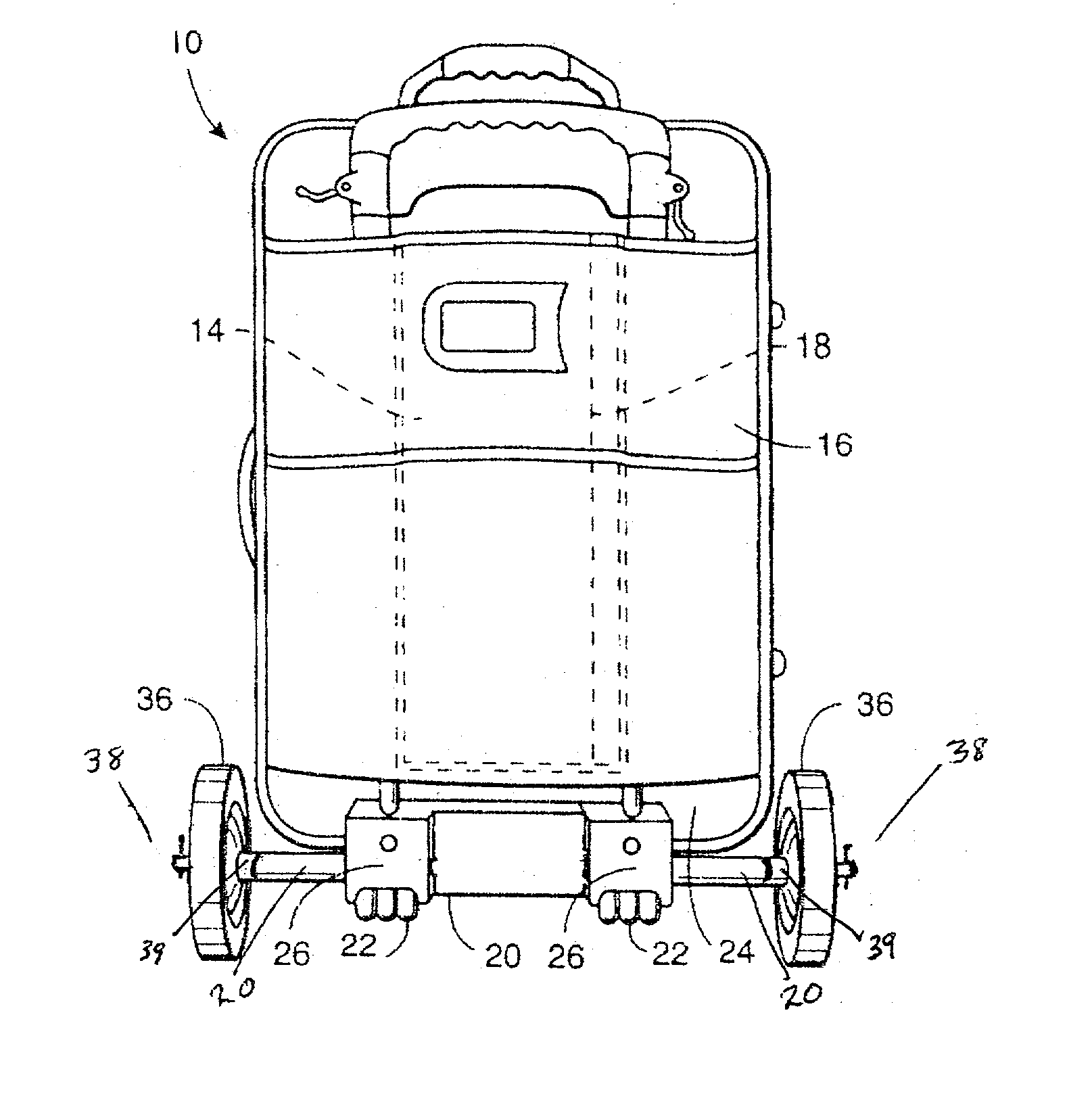
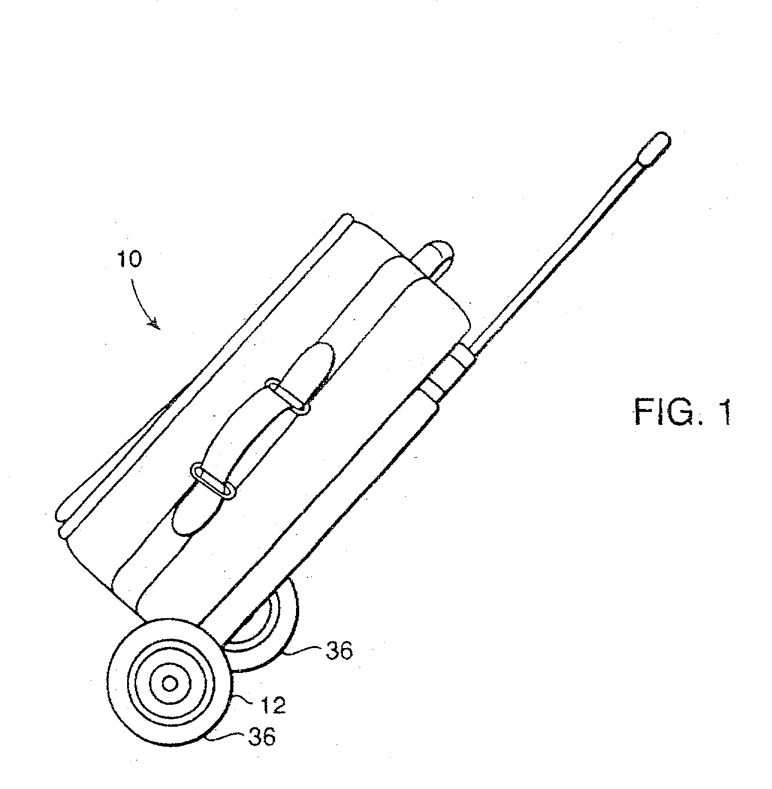
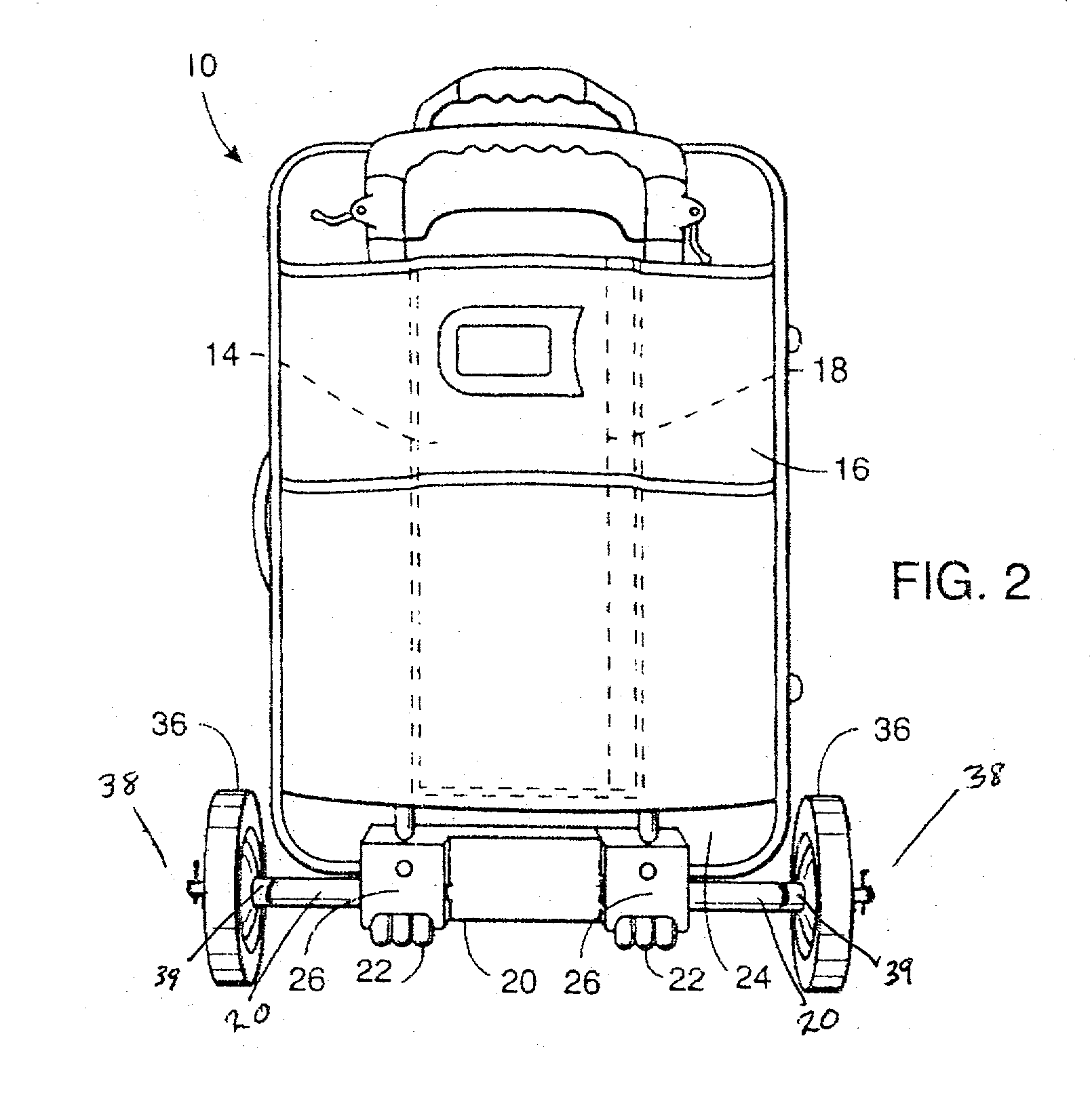
[0018] As shown in the drawings, a preferred embodiment of the invention has a conventional carry-on luggage case 10 with a removable large wheel assembly 12 in place. Luggage case 10 has a pouch or pocket 14 attached to it's exterior side 16 to receive the two large wheels.

[0019] The luggage case 10 is provided with conventional small wheels 22 secured to the bottom portion 24 of the luggage case 10 with mounting blocks 26. Holes 28 and 30 are drilled in the mounting blocks 26 to receive the sleeves 20 which will receive the axles 21. Luggage that does not permit the drilling of such holes must have suitable mounting blocks (not shown) added to the bottom portion of the luggage and suitable holes provided therein.

[0020] The sleeves 20 maintain the large wheels 36, with the tubular extension 39 on the inner side, in a position away from the sides of the luggage case 10. Fasteners 38 at the ends of axles 21 keep the large wheels 36 from falling off axle 21. While there are several ty...


PUM


Abstract

A removable large wheel assembly having two permanent sleeves inserted in holes drilled in the small wheel mounting blocks, two axles, one in each of the sleeves of the mounting blocks, with a permanent stop at one end and a fastener at the opposite end of each axle, said axles being inserted through sleeves of the mounting blocks of the small wheels or, if not possible through the existing small wheel mounting blocks, through holes drilled for sleeves through additional mounting blocks added to the bottom of the luggage and the large wheels having an extended tubular part at the hub of the inner side of each wheel, this part being molded as part of the wheels and of sufficient length so that when each wheel is placed on it's axle with the extended part facing inward toward the luggage the wheel is prevented from touching the outer edge of the luggage. These axles are inserted through the tubular sleeves which are permanently in place in the mounting blocks referred to above to give support and ease of movement. When in place, the permanent stop is on the inner end of the axles. The axle can now be extended outward to accept the large wheel and a fastener added to keep the wheel in place. When not in use the axle can be retracted back into the sleeve. The assembly makes transporting the luggage easier and more stable. The wheels stay on the luggage at all times but can be removed easily if necessary.

Description

[0001] At the present time, carry-on luggage for travel by aircraft is usually provided with wheels to aid in their transport and improve mobility. Such wheels are restricted in size to allow maximum sizefor the luggage itself which is limited in extent by the airlines. For example, United Airlines restricts carry-on luggage to 22 by 13 by 9 inches. British Airlines restricts carry-on luggato 22 by 16 by 8 inches.[0002] Even larger luggage, which must be checked, is generally provided with relatively small wheels to allow maximum size for the luggage case. Such larger luggage, even with a front set of wheels and a back set of wheels can be unstable and can be easily overturned when being pushed or pulled in their transport.[0003] Accordingly, there is a need for means providing such luggage with larger wheels for greater mobility and ease in transport but which can be removed when no longer needed so that carry-on luggage meets airline requirements and larger luggage can be checked ...

Claims


Application Information

Patent Timeline
Patent Type & Authority Applications(United States)
IPC IPC(8): A45C5/14B62B1/12
CPCA45C5/143B62B2205/10B62B2202/24B62B1/125
Inventor EDWARDS, ANTHONY G.
Owner EDWARDS ANTHONY G
Why Eureka
Try Eureka