Earphone cable-receiving device with power recharge function

a technology of power recharge and earphone cable, which is applied in the direction of current supply arrangement, transportation and packaging, substation equipment, etc., can solve the problems of inability to recharge batteries, communication cables that cannot be outwardly held in a stable manner, and inability to recharging batteries

Inactive Publication Date: 2003-07-31
LIAO SHENG HSIN
View PDF1 Cites 55 Cited by
  • Summary
  • Abstract
  • Description
  • Claims
  • Application Information

AI Technical Summary

Benefits of technology

[0010] With the above earphone cable-receiving device, the first connector can be removably connected to a power source while the second connector is connected to a portable electrical device. Via the power recharge unit, the portable electrical device can be thereby recharged. With the possibility of connecting various types of power sources, the recharge of the portable electrical device via the earphone cable-receiving device further can be convenient and user-friendly.

Problems solved by technology

Because the spring elements of the traditional cable-receiving structures exert a substantial retraction tension on the communication cables pulled out, the communication cables therefore usually cannot be outwardly held in a stable manner.
A utilization of the communication cables can be thereby substantially impeded.
As briefly described above, the conventional cable-receiving cases are strictly provided with cable-winding / retraction function and are not capable of recharging batteries.
Furthermore, the traditional power recharge devices are usually capable of performing a simple type of recharging operation, which thus renders their fields of utilization substantially limited.
As a result, the use of traditional cable-receiving cases and power recharge devices thus presents various inconveniences that may be improved.

Method used


Image

  • Earphone cable-receiving device with power recharge function
  • Earphone cable-receiving device with power recharge function
  • Earphone cable-receiving device with power recharge function

Examples


Embodiment Construction

[0021] Wherever possible in the following description, like reference numerals will refer to like elements and parts unless otherwise illustrated.

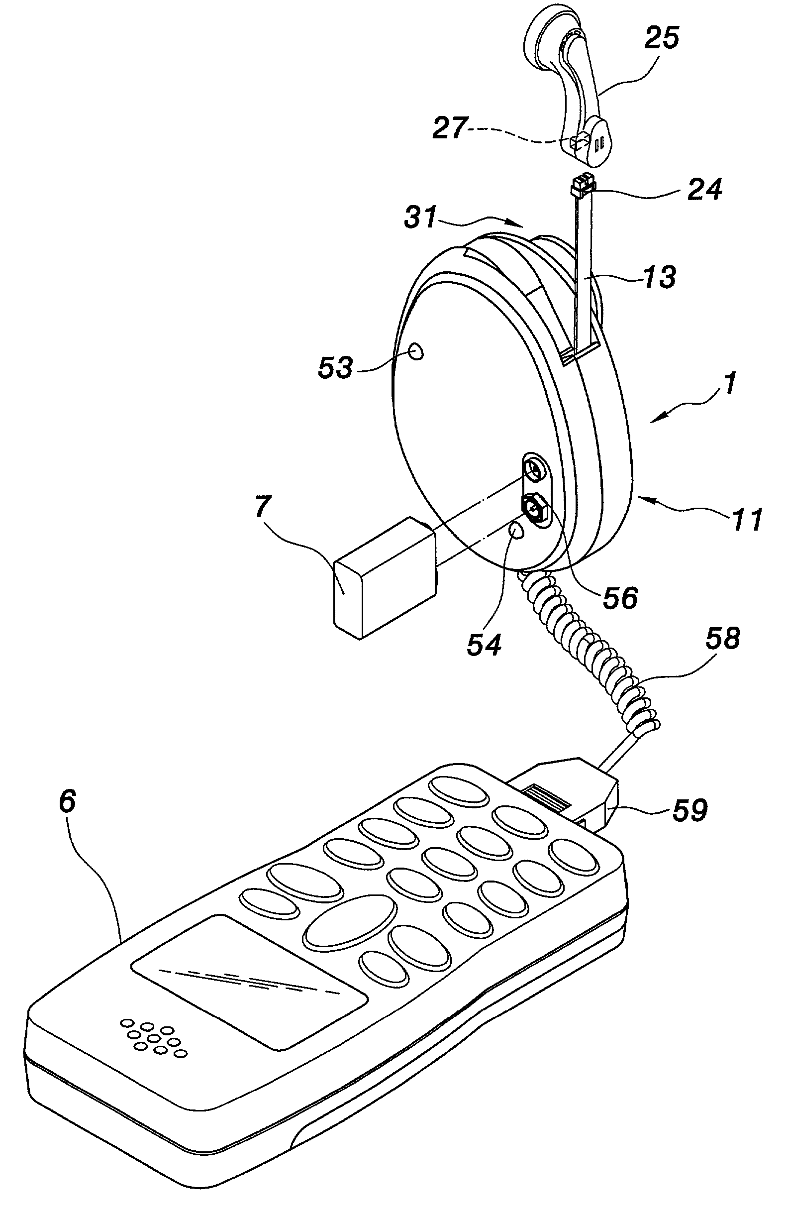
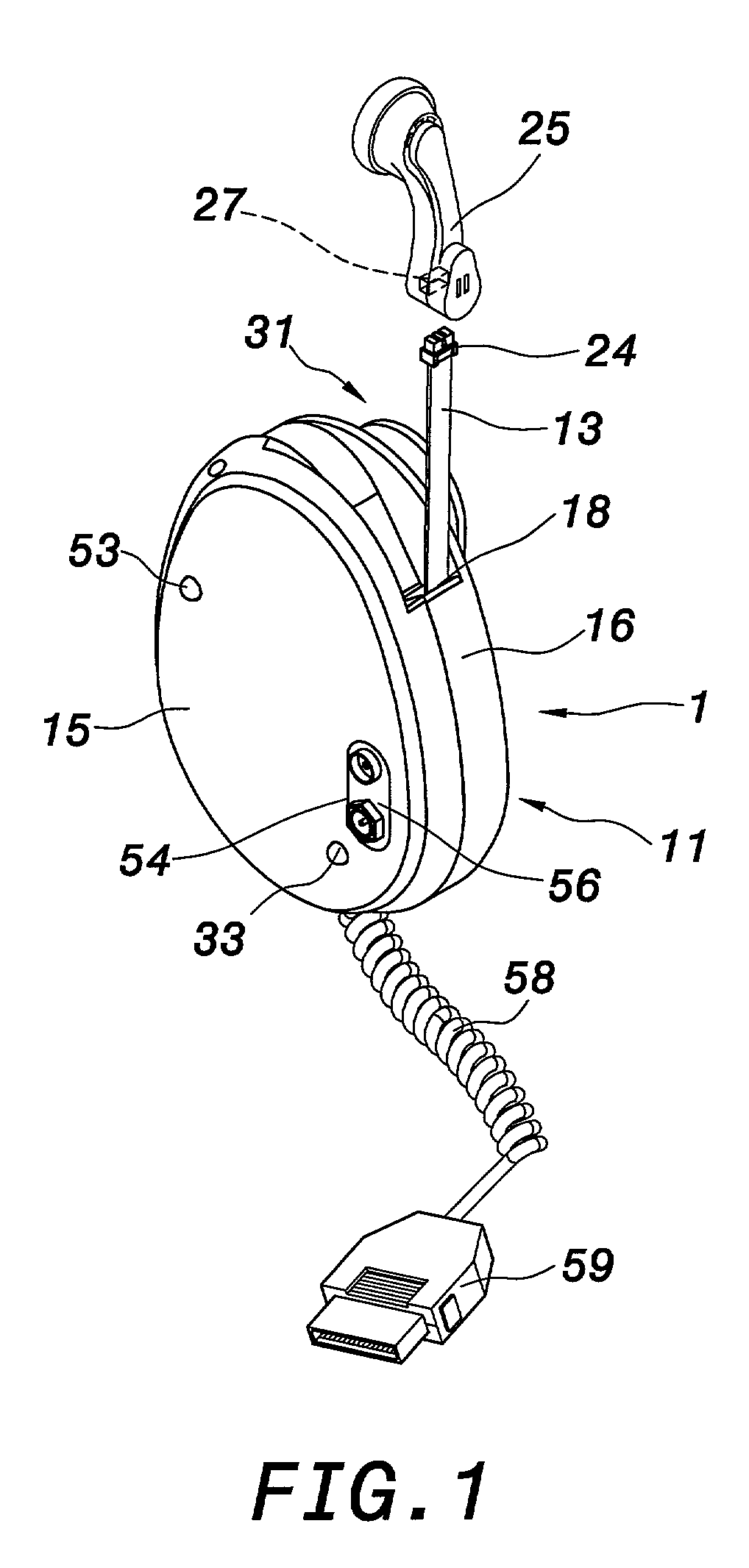
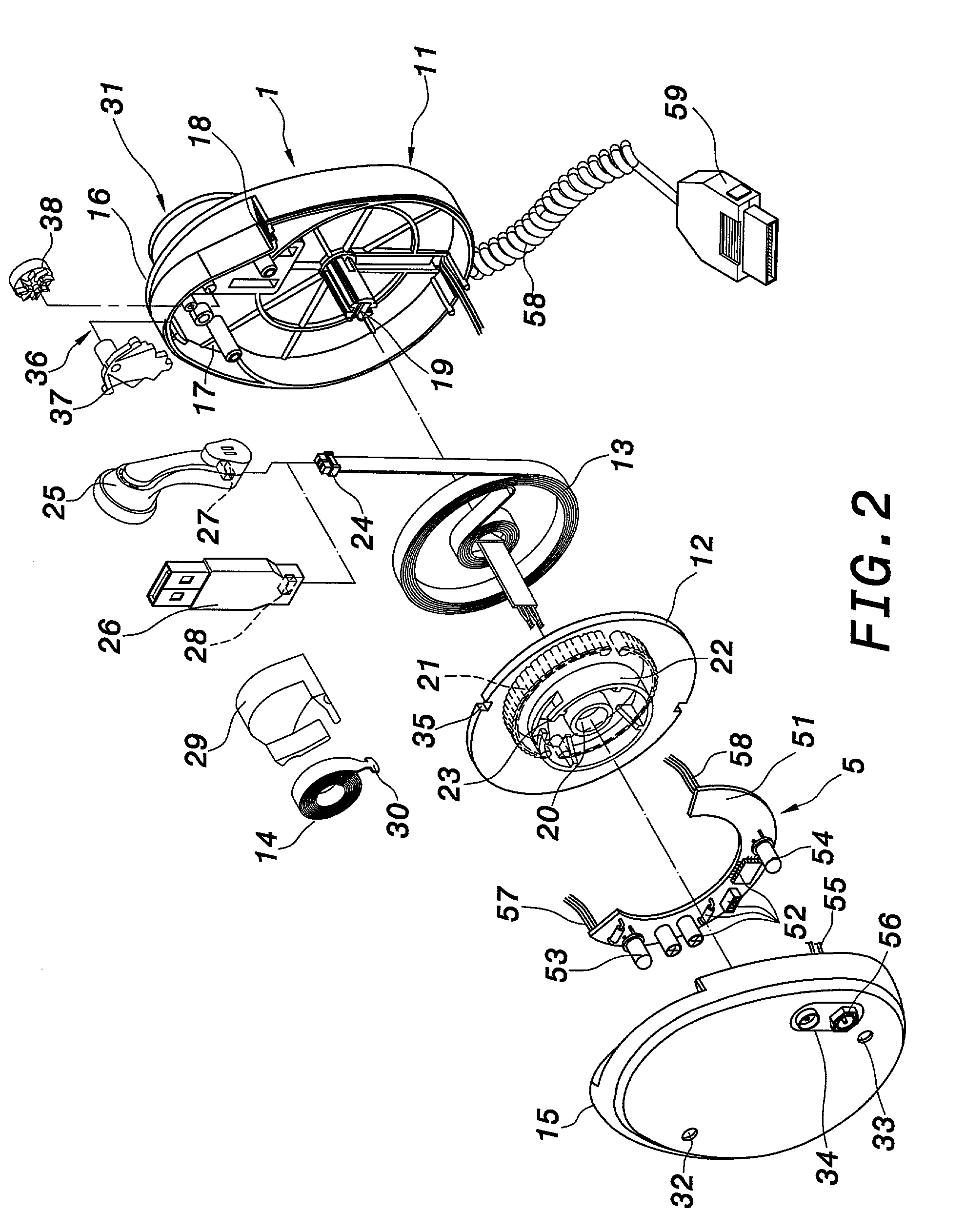
[0022] Referring to FIG. 1 through FIG. 3, various views schematically illustrate an earphone cable-receiving device with power recharge function according to a first embodiment of the invention. The earphone cable-receiving device comprises a cable-receiving structure 1 and a power recharge unit 5. The cable-receiving structure 1 may be formed into any adequate shape according to specific design choices. In this embodiment, the cable-receiving structure 1 comprises an outer case 11, a cable-winding plate 12, a communication cable 13, and a spiral spring 14. The outer case 11 is included an upper case 15 and a lower case 16 that are assembled with each other via fastening engagement or screw assembly to define an hollow space. A cable-receiving cavity 17 is thereby defined within the outer case 11 to receive the communication cable 13. A c...


PUM


Abstract

An earphone cable-receiving device includes a cable-receiving structure and a power recharge unit. The cable-receiving structure includes an outer case, a cable-winding plate, a communication cable, and a spiral spring. The cable-winding plate and the spiral spring, connected to each other, are further received within the outer case. The communication cable is wound on the cable-winding plate, and further has an external terminal mounted with a first connector that can removably connect an earphone. The power recharge unit is mounted into the outer case and is further connected to the communication cable. The power recharge unit is further connected to a second connector via a transmission cable to recharge a portable electrical device connected to the second connector. Thereby, various types of power sources can be connected to the earphone cable-receiving device to recharge the portable electrical device.

Description

[0001] 1. Field of the Invention[0002] The invention relates to an earphone cable-receiving device with power recharge function. More particularly, the invention provides an earphone cable-receiving device with power recharge function that can recharge a portable electrical device from various types of power sources such as portable computers, power recharge terminals of automobile, or dry battery.[0003] 2. Description of the Related Art[0004] As electrical and telecommunication appliances become popular, communication cables are increasingly present in our environment to connect various types of devices. To prevent too long and numerous communication cables from being interlaced or knotted with one another or, on the contrary, to avoid too short communication cables incompatible with a practical use, The cable-receiving structures for communication devices been developed various types. The cable-receiving structures of the prior art are similarly based on a principal structure that...

Claims


Application Information

Patent Timeline
Patent Type & Authority Applications(United States)
IPC IPC(8): H02J7/00H04M1/15H04M19/08
CPCH02J7/0054H04M19/08H04M1/15H02J7/342
Inventor LIAO, SHENG HSIN
Owner LIAO SHENG HSIN
Why Eureka
Try Eureka