

Sensor manifold for a flow sensing venturi
a flow sensing venturi and sensor manifold technology, applied in the field of flow sensing venturi, can solve the problems of tight space constraints, further complicated maintenance, etc., and achieve the effect of simplifying in-situ removal and replacemen
- Summary
- Abstract
- Description
- Claims
- Application Information
AI Technical Summary
Benefits of technology
Problems solved by technology
Method used
Image


Examples
Embodiment Construction
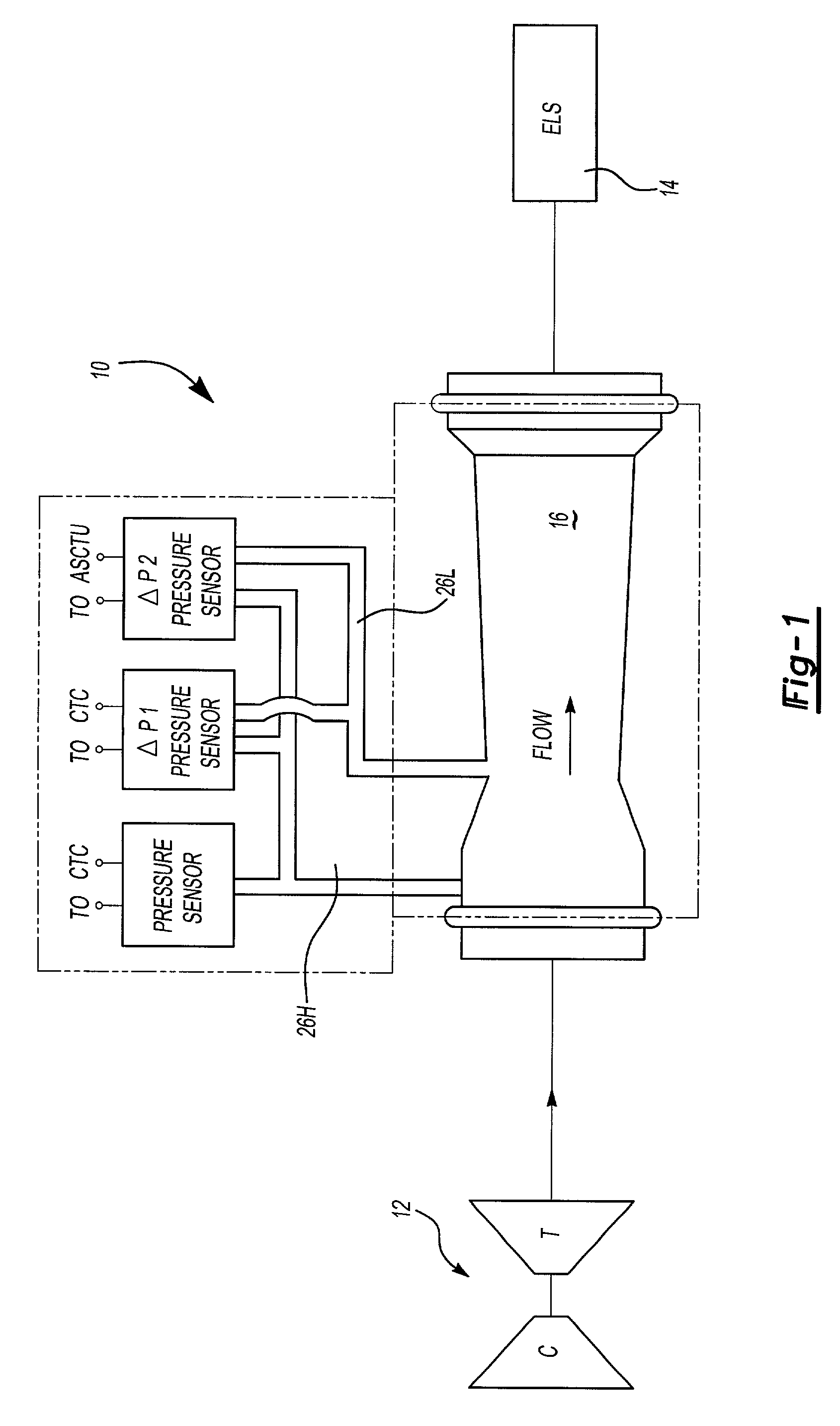
[0015] FIG. 1 illustrates a general schematic view of a flow sensing venturi system 10. The flow sensing venturi system 10 is preferably located in a bleed air line from a gas turbine engine (illustrated schematically at 12) as part of an aircraft Environmental Control System (ECS; illustrated schematically at 14). It should be understood that other high-pressure fluid flow systems will also benefit from the present invention.
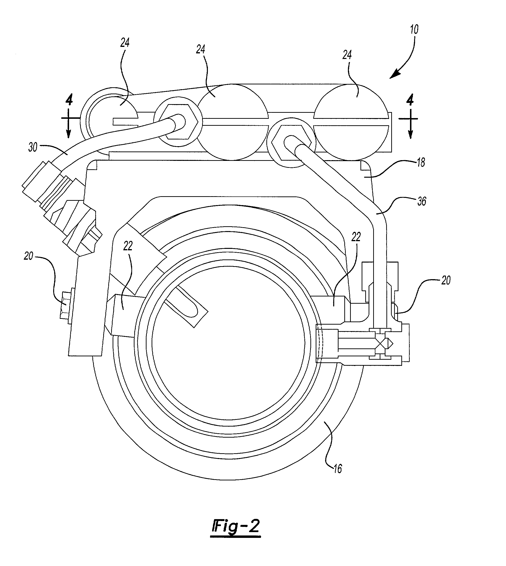
[0016] Referring to FIG. 2, the flow sensing venturi system 10 includes a venturi body 16 and a manifold 18 mounted thereto. A multiple of sensors 20 communicate with the interior of the venturi body 16 through the manifold 18. As generally known, the venturi body 16 provides for measurement of fluid flow therethrough. The venturi body defines a flow axis F.
[0017] The manifold 18 is mounted to the venturi body 16 by fasteners 21 which are threaded into bosses 22 extending from the venturi body 16. The manifold 18 is preferably formed as a bridge-like structure ...
PUM
 Abstract
Description
Claims
Application Information