
Mounting system, sail, steering mechainism and frame for a landsailer

a technology of mounting system and mechainism, which is applied in the direction of steering control, floating buildings, propulsive elements, etc., can solve the problems of landsailer capsize, limited healing ability in response to lateral forces, and limited manoeuvrability

Inactive Publication Date: 2003-08-07
BLOKART INT
View PDF15 Cites 8 Cited by
  • Summary
  • Abstract
  • Description
  • Claims
  • Application Information

AI Technical Summary

Benefits of technology

[0006] Thus, it is an object of the present invention to overcome or at least alleviate problems in landsailers at present or at least to provide the public with a useful choice.
[0018] Preferably, the down-haul may be secured to the frame of the landsailer through a cleat accessible from a cockpit, thereby allowing variation of the tension applied to the down-haul while the landsailer is in motion.

Problems solved by technology

As a landsailer must travel over solid ground, its ability to heal over in response to these lateral forces is limited.
If the land vehicle does heal over it tends to be unstable as its resistance to movement is low and hence the landsailer tends to capsize.
Thus, if there is a sudden gust of wind or a sudden change in wind angle, then there is a risk that the landsailer will capsize.
This risk of capsizing limits the manoeuvrability of the landsailer, creating a disadvantage, particularly in a race situation.
A problem with landsailers is that they are typically large and therefore difficult to store, handle and transport.
This can reduce the enjoyment of use of the landsailer for recreational purposes.
Also, many landsailers are difficult and time consuming to erect.
Further, landsailers at present are typically complex devices which involve significant costs of manufacture.

Method used


Image

  • Mounting system, sail, steering mechainism and frame for a landsailer
  • Mounting system, sail, steering mechainism and frame for a landsailer
  • Mounting system, sail, steering mechainism and frame for a landsailer

Examples


Embodiment Construction

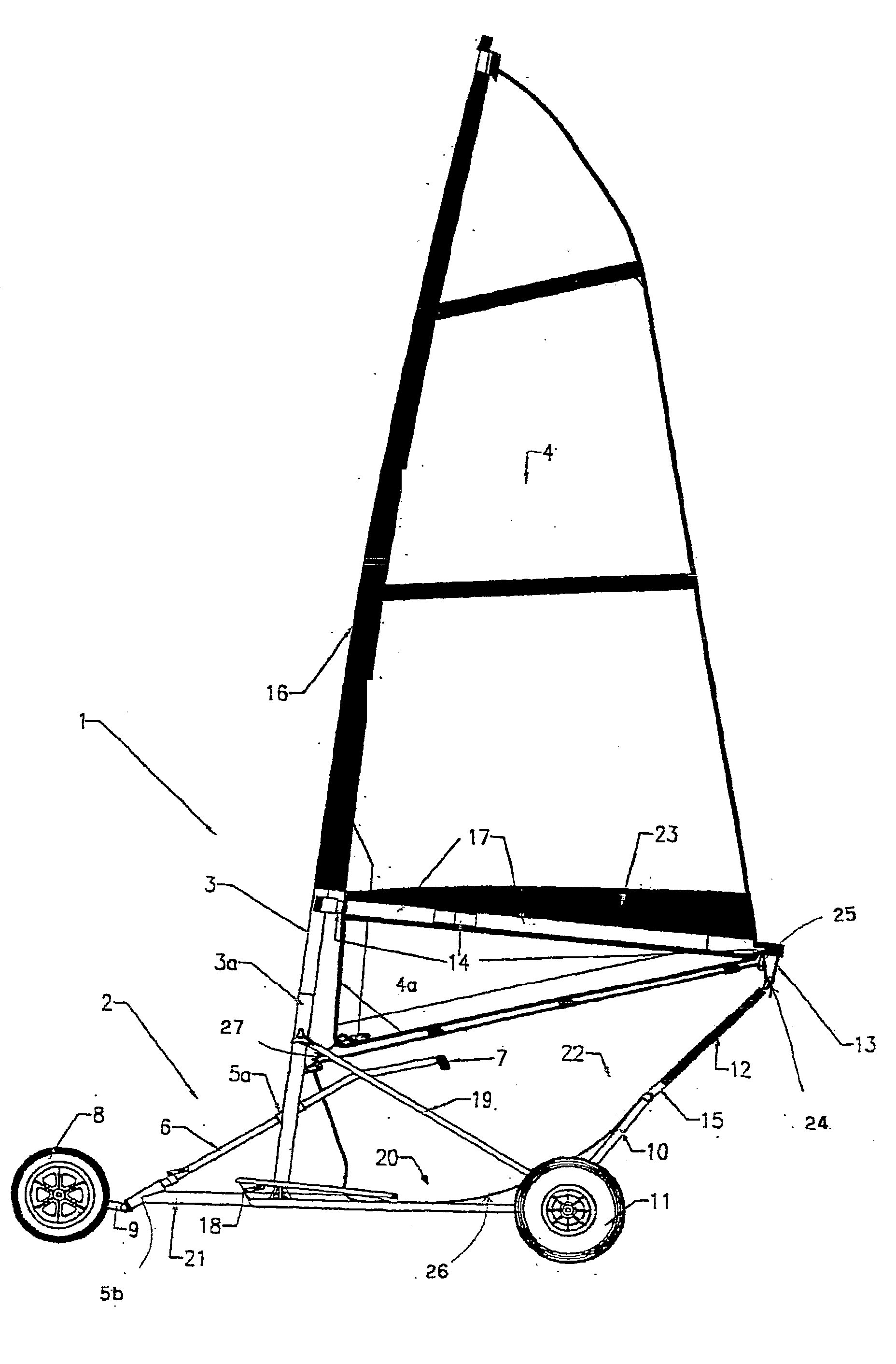
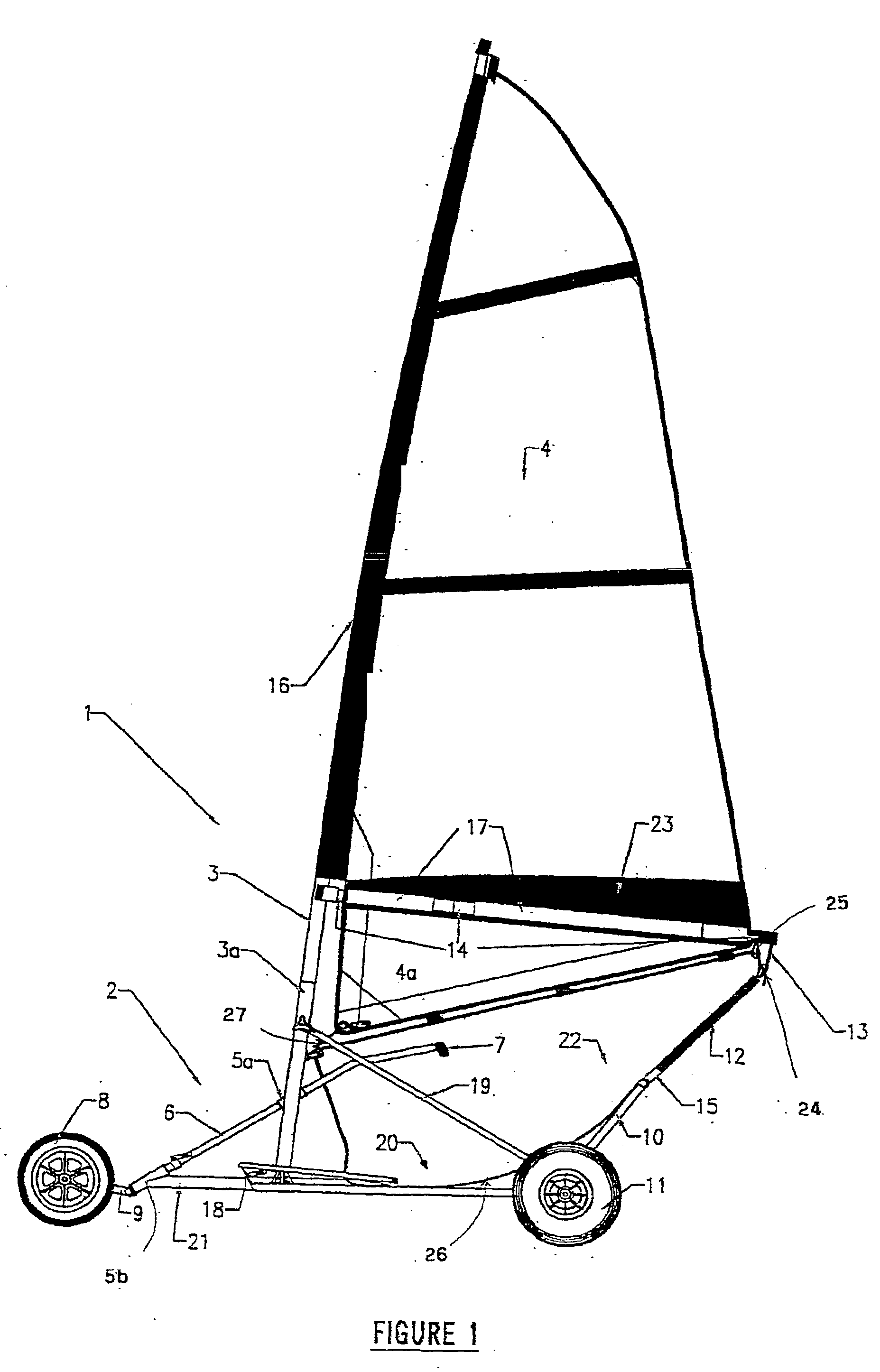
[0036] Referring first to FIG. 1 of the accompanying drawings, a schematic representation of a side view of a landsailer, generally referenced 1 is shown. The landsailer includes a frame generally referenced 2, a mast 3 within a mast receptacle 3a and a sail 4.

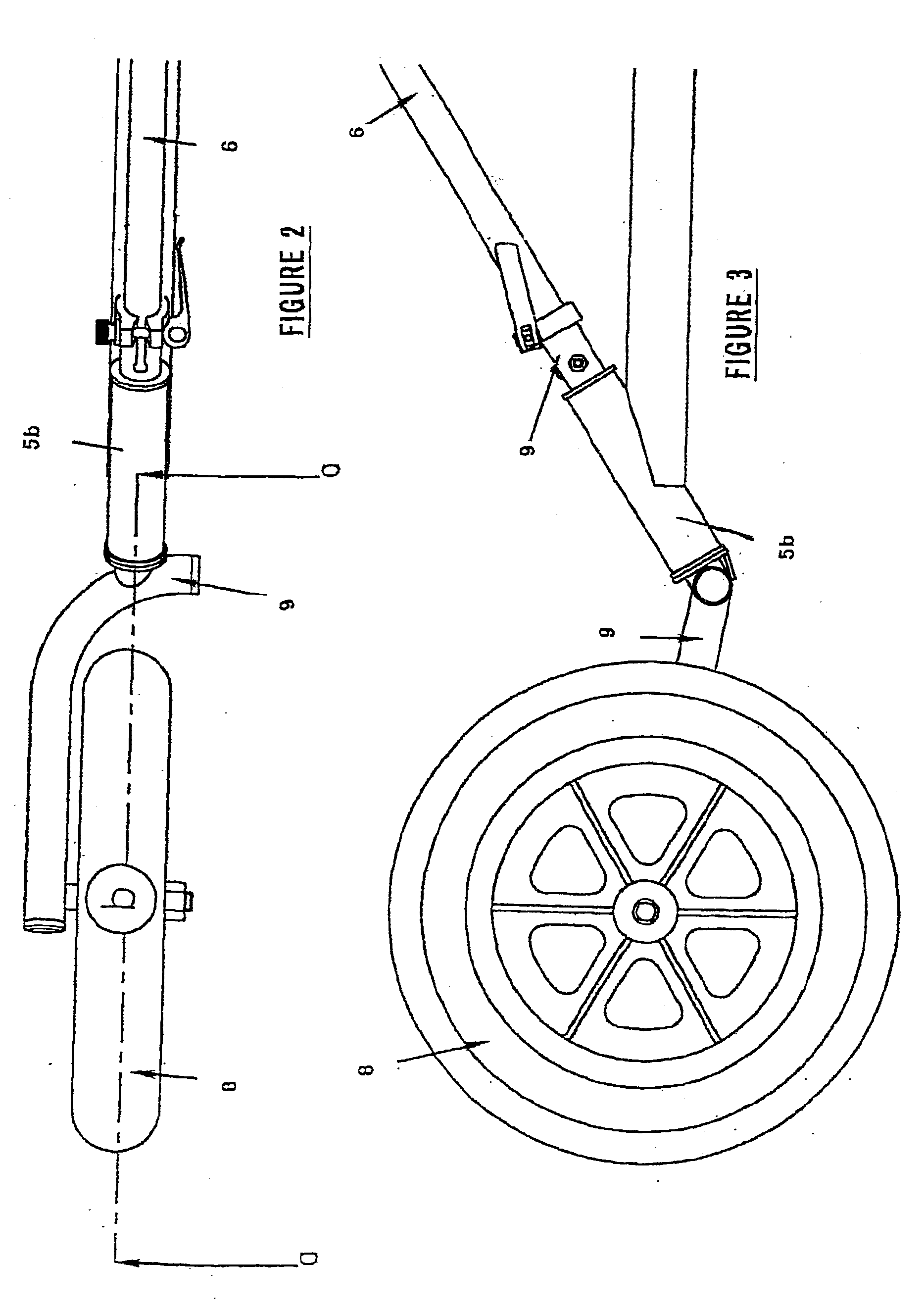
[0037] The frame 2 includes a cockpit section 20, a steering section 21 and a saddle section 22. The mast receptacle 3a includes an aperture 5a and the steering section 21 includes an aperture 5b. A tiller arm or shaft 6 is inserted through apertures 5a and 5b. The apertures 5a and 5b securely hold the shaft 6 in place, while allowing rotation of the shaft 6. The shaft 6 includes a handle 7 which the driver uses to control the direction of movement of the landsailer 1. A bend may be provided in the shaft 6 between the portion inserted in aperture 5a and the handle 7 to allow movement of handle 7 along an arc to effect rotational movement of the shaft 6. This steering mechanism provides a simple construction with increased cont...


PUM


Abstract

A mounting system for a boom (14) of a landsailer (1) includes a resilient flexible member (12), at one end engageable with a rearward portion of the landsailer frame (2) and at the other end with the main sheet (13). A steering mechanism includes a shaft (6) which extends through an aperture (5a) in the mast (3) or mast receptacle (3a) and an aperture (5b) in the frame (2). A wheel (8) is connected to one end of the shaft (6) and the driver operates the other end of the shaft (6). The frame (2) includes a cockpit section (20), mast receptacle (3a), saddle frame (10) and steering section (21) each engageable to form the landsailer frame (2). The dimensions of each part of the mast receptacle (3a), saddle frame (10) and steering section (21) are equal or smaller than the dimensions of the cockpit section (20). The sail (4) includes a pocket (17) to receive the boom (14), and a lower sail portion (4a) extending below the pocket (17).

Description

[0001] Landsailers are well known recreational transport devices which utilise sail power for propulsion. The use of landsailers has gained in popularity over recent times as a recreational and sporting activity.[0002] In comparing landsailers to yachts, a fundamental difference is that yachts can easily heal over in response to lateral forces applied by the wind on the sails. This healing action helps to absorb impact forces caused by changes in wind strength as well as reducing the apparent area of the sail or sails. As a landsailer must travel over solid ground, its ability to heal over in response to these lateral forces is limited. If the land vehicle does heal over it tends to be unstable as its resistance to movement is low and hence the landsailer tends to capsize.[0003] Thus, if there is a sudden gust of wind or a sudden change in wind angle, then there is a risk that the landsailer will capsize. One situation where this is particularly apparent is when the landsailer is tr...

Claims


Application Information

Patent Timeline
Patent Type & Authority Applications(United States)
IPC IPC(8): B62B15/00B63B35/79
CPCB62B15/001B63B35/7969B62B15/004B63H8/22
Inventor BECKETT, PAUL FRANCIS
Owner BLOKART INT
Learn More