
Printer With Mechanism For Controlling Recording Medium Tension

a recording medium and tension control technology, applied in printing, other printing apparatus, etc., can solve the problems of affecting print quality, affecting print quality, and affecting good print quality, so as to reduce tension on recording medium, minimize variation in tension (or variation in slack), and improve precision

Active Publication Date: 2015-07-30
SEIKO EPSON CORP
View PDF1 Cites 0 Cited by
  • Summary
  • Abstract
  • Description
  • Claims
  • Application Information

AI Technical Summary

Benefits of technology

This patent describes a method that reduces tension and variation in tension on a recording medium, which improves print quality. The method detects the position or movement of a movable member and controls the supply speed of the recording medium accordingly. This allows for precise conveyance of the recording medium and maintains good print quality.

Problems solved by technology

When deviation in the conveyance speed of the recording medium occurs, deviation also occurs in the positioning of the printed dots, and good print quality cannot be maintained.
As a result, print quality is adversely affected.
When printing on a recording medium with high rotational inertia, such as roll paper, a heavy acceleration load is applied to the recording medium immediately after acceleration, which can greatly affect the print quality.
As a result, the conveyance speed of the recording medium can fluctuate greatly and maintaining good print quality can be difficult.
Because decreasing the tension on the recording medium is difficult, or decreasing the range of tension variation or the range of variation in slack is difficult, with this method, the conveyance speed of the recording medium can vary greatly and print quality can easily drop.
As a result, the motor that drives the media supply mechanism spins freely or starts rocking, and can possibly burn out.

Method used


Image

  • Printer With Mechanism For Controlling Recording Medium Tension
  • Printer With Mechanism For Controlling Recording Medium Tension
  • Printer With Mechanism For Controlling Recording Medium Tension

Examples


embodiment 1

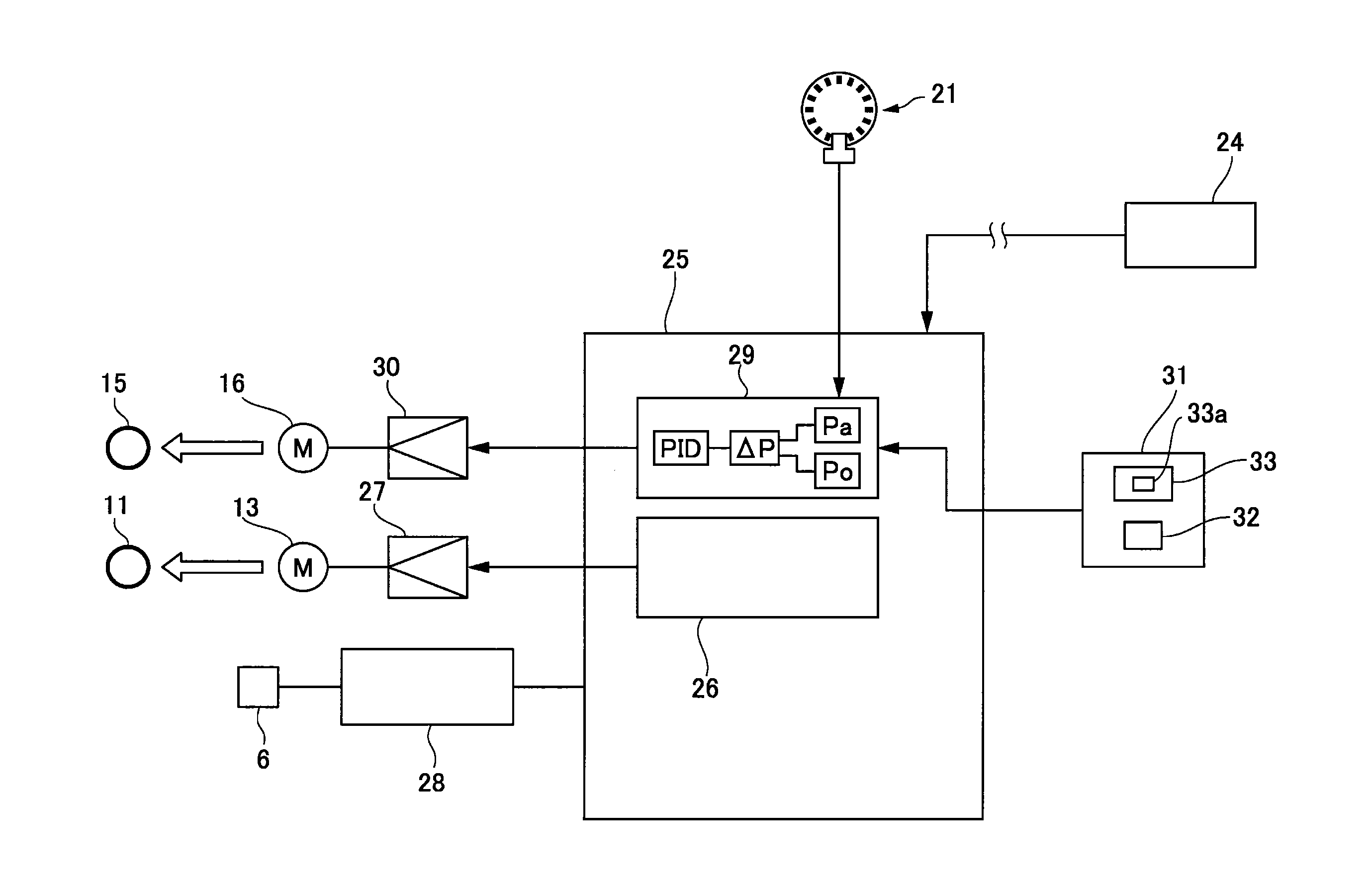
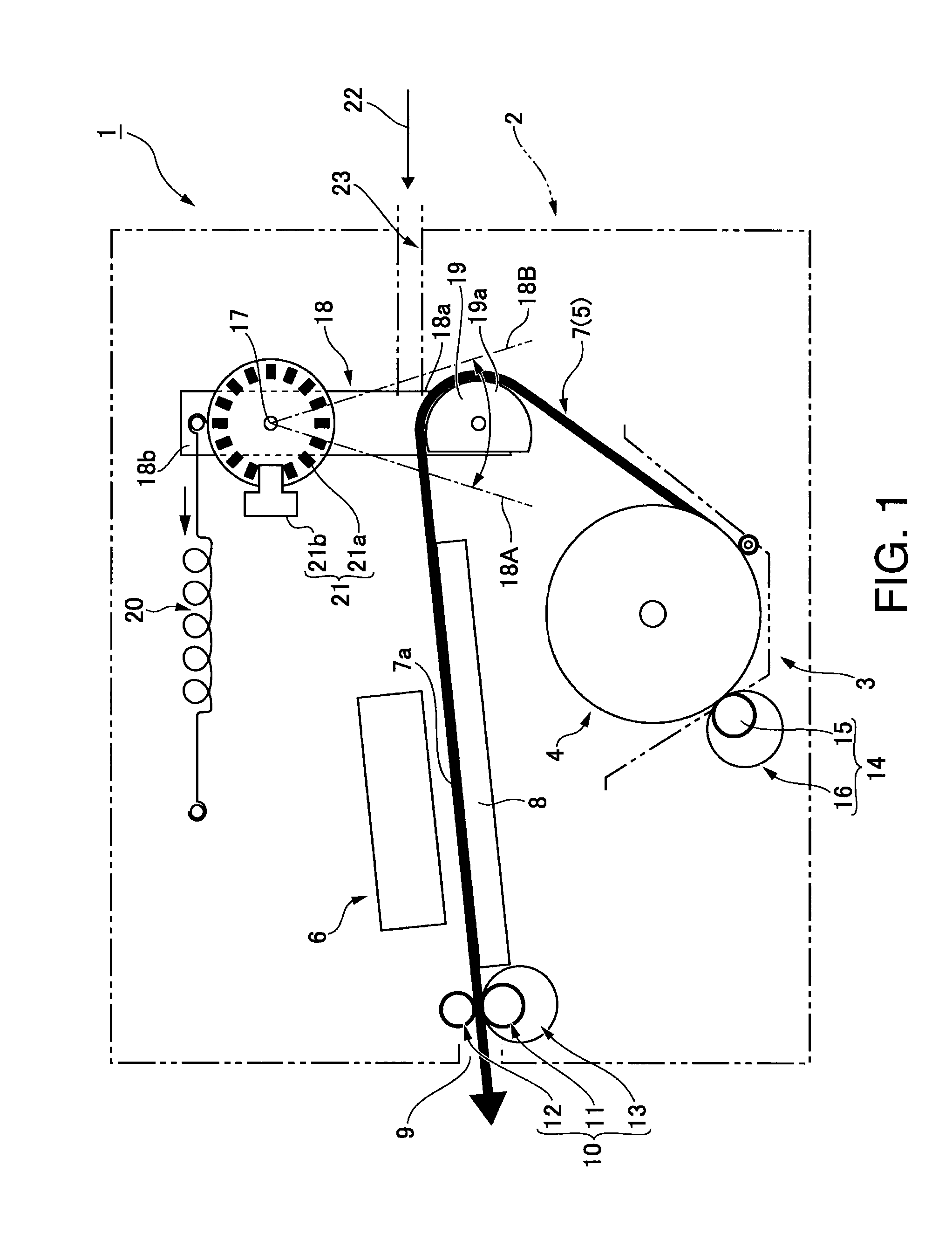
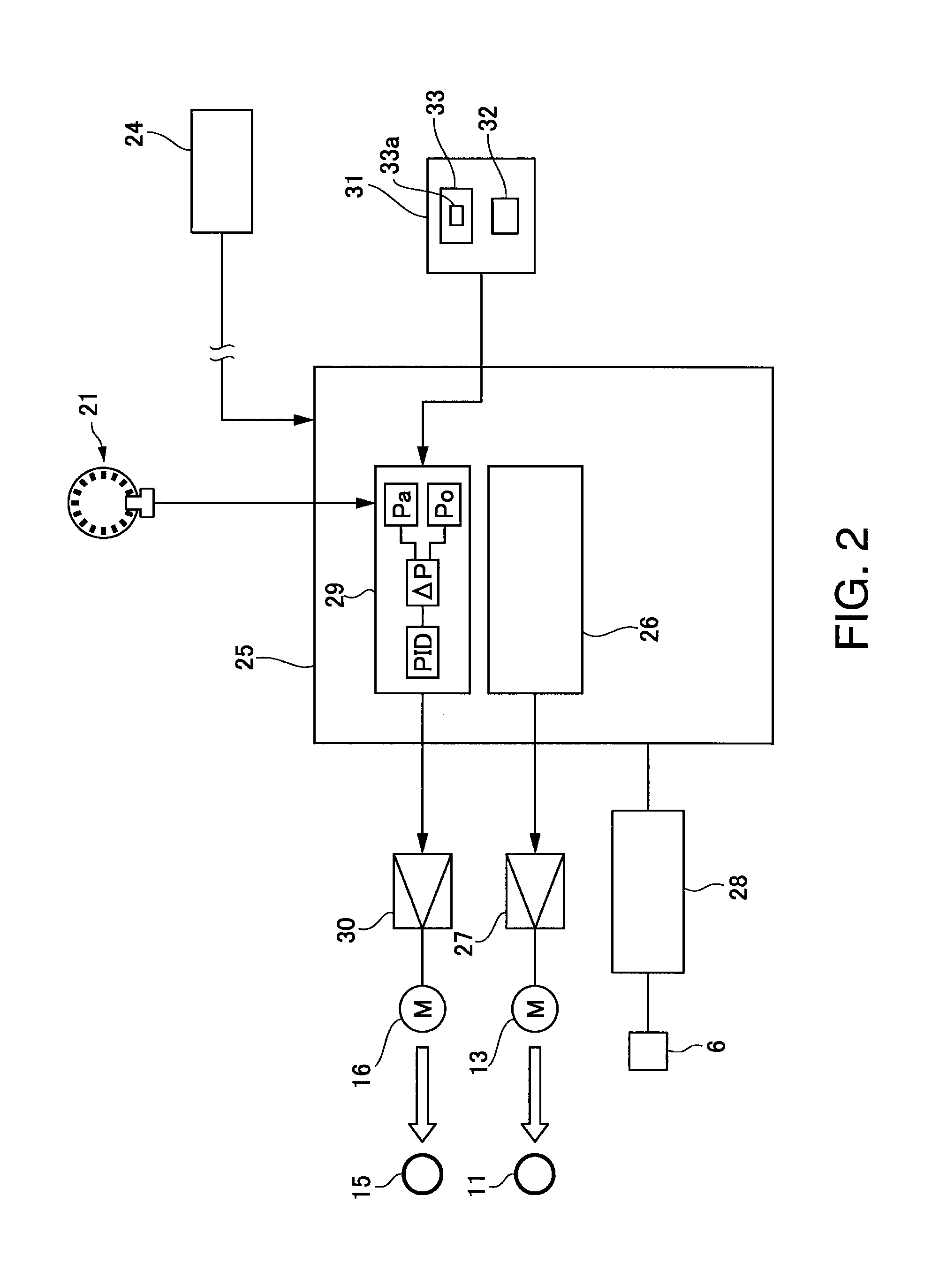
[0033]FIG. 1 schematically describes an inkjet line printer according to the first embodiment of the disclosure.

[0034]This inkjet line printer 1 (referred to below as simply printer 1) is a roll paper printer, and has a roll paper compartment 3 inside a printer cabinet 2 denoted by an imaginary line in the figure. A line printhead 6 (inkjet head) prints on continuous paper 5 of a specific width that is fed from a paper roll 4 stored in the roll paper compartment 3. The line printhead 6 has as row of ink nozzles that eject ink droplets, and the length of the ink nozzle row covers the maximum width of the continuous paper 5 that can be conveyed.

[0035]A media conveyance path 7 is formed inside the printer cabinet 2 as indicated by the bold line. The media conveyance path 7 travels from the roll paper compartment 3 past the printing position 7a of the printhead 6 to a media exit 9 disposed, for example, in the front of the printer cabinet 2. The printing position 7a on the media conveya...

embodiment 2

[0064]FIG. 4 schematically describes an inkjet line printer according to a second embodiment of the disclosure. The basic configuration of this inkjet line printer 1A is identical to the printer 1 described above, like parts are identified by like reference numerals, and further description thereof is omitted.

[0065]This inkjet line printer 1A uses a belt-type media conveyance mechanism 10A as the media conveyance mechanism. This belt-type media conveyance mechanism 10A has a conveyance belt 51, a plurality of guide rollers 52 to 56 on which the conveyance belt 51 is mounted, a belt drive roller 57 that drives the conveyance belt 51, and a conveyance motor 58 that rotationally drives the belt drive roller 57. One guide roller 52 is pressed to the belt drive roller 57 with the conveyance belt 51 therebetween. The conveyance belt 51 has a conveyance belt portion 51a spanning the part of the media conveyance path 7 including the printing position 7a of the printhead 6. A pinch roller 59...


PUM


Abstract

A inkjet printer has a mechanism to counter change in the tension of the recording medium to convey the recording medium with more precision. In a method, the position or movement of a movable member is detected by a detector, and the recording medium is conveyed based on output from the detector so that the movable member is maintained in or urged back to a set position. Also, one or more operations are stopped when the movable member moves outside of an allowable movement range. Which operation(s) is or are stopped depends on whether the movable member moves outside its allowable range in a direction that increases or decreases the tension in the recording medium.

Description

CROSS-REFERENCE TO RELATED APPLICATIONS[0001]This application is a continuation of, and claims priority under 35 U.S.C. §120 on, U.S. application Ser. No. 14 / 147,861, filed Jan. 6, 2014, which claims priority under 35 U.S.C. §119 on Japanese patent application no. 2013-002369, filed Jan. 10, 2013. The content of each such related application is incorporated by reference herein in its entirety.BACKGROUND[0002]1. Technical Field[0003]The present disclosure relates to a method of printing and controlling a printer that can suppress variation in the tension of recording media.[0004]2. Related Art[0005]Inkjet and other types of printers print on a recording medium by driving a printhead synchronized to conveyance of the recording medium continuously or intermittently. When deviation in the conveyance speed of the recording medium occurs, deviation also occurs in the positioning of the printed dots, and good print quality cannot be maintained.[0006]For example, if the back tension applied...

Claims


Application Information

Patent Timeline
Patent Type & Authority Applications(United States)
IPC IPC(8): B41J13/00B41J2/01
CPCB41J2/01B41J13/0009B41J15/165B41J11/007B41J15/16
Inventor HORAGUCHI, NORIO
Owner SEIKO EPSON CORP
Learn More