Floating offshore structures

a technology of floating structures and offshore structures, applied in the direction of floating buildings, anchoring arrangements, vessel construction, etc., can solve the problems of hydrostatic pressure on the buoyancy structure, high amount of excess buoyancy and high tension in the cables, and the instability of the offshore structure, etc., to achieve simple and cost-effective solutions, and add buoyancy to the system

Inactive Publication Date: 2015-01-01
GE RENEWABLE TECH WIND BV
View PDF3 Cites 1 Cited by
  • Summary
  • Abstract
  • Description
  • Claims
  • Application Information

AI Technical Summary

Benefits of technology

[0012]Having at least one opening dimensioned such that sea water can flow into and out of the connecting structure ensures that inside the connecting structure the water level will correspond to the sea level. Thus the connecting structure does not add buoyancy to the system. As a result, no extra buoyancy would be added by the connecting structure when the sea level becomes higher and no reduction of buoyancy would affect the offshore structure when the sea level becomes lower. Buoyancy variations due to waves or tide changes can thus be avoided or at least substantially reduced.
[0013]This is a simple and cost-effective solution. It can be easily implemented in current TLPs offshore structures e.g. by drilling at least one hole of the appropriate dimensions in the connecting structure, i.e. a hole that allows sea water to flow into and out of the connecting structure.
[0014]In some embodiments, the connecting structure may further comprise one or more breathing orifices arranged such that in use they normally remain above the sea level. This enhances the natural flow of water into and out of the connecting structure as it reduces the risk of vacuum generation within the connecting structure e.g. when water flows into, thus ensuring no air providing buoyancy remains inside the connecting structure when the sea level increases.

Problems solved by technology

In order for these structures to be stable, the mooring lines must always be under tension; otherwise the offshore structure could become unstable and could fall over.
Since the loads on the offshore structures, and particularly on a floating wind turbine may vary considerably both in magnitude and direction, a high amount of excess buoyancy and high tension in the cables may be required.
Furthermore, like any body submerged in water, buoyancy structures are subject to hydrostatic pressure on the outer walls that are in contact with the sea water, and consequent buckling.

Method used


Image

  • Floating offshore structures
  • Floating offshore structures
  • Floating offshore structures

Examples


Embodiment Construction

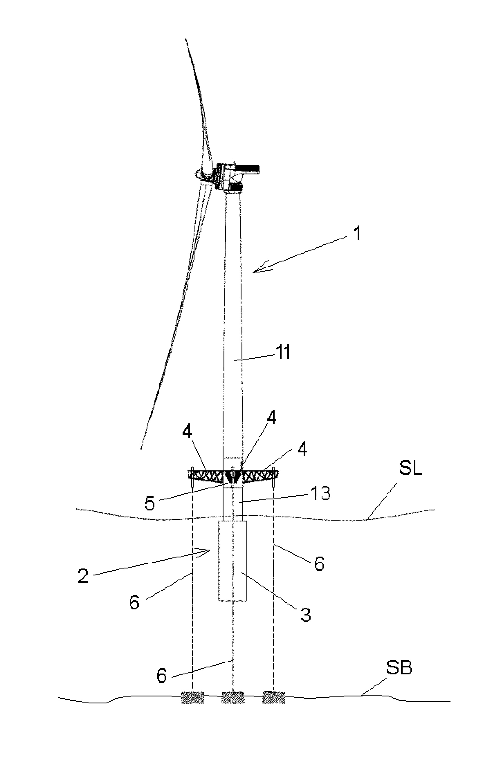
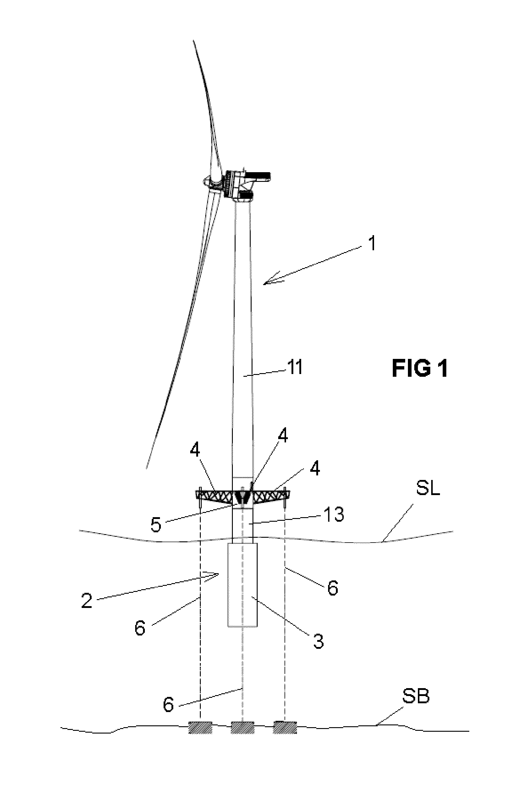
[0027]FIG. 1 shows an example of an offshore wind turbine of the TLP (Tension Leg Platform) type having arms 4 that in use remain above the sea level.

[0028]All throughout the present description and claims, the expression “sea level” should be understood to cover all possible heights of the surface of the sea including the highest and lowest tides and including variations due to waves.

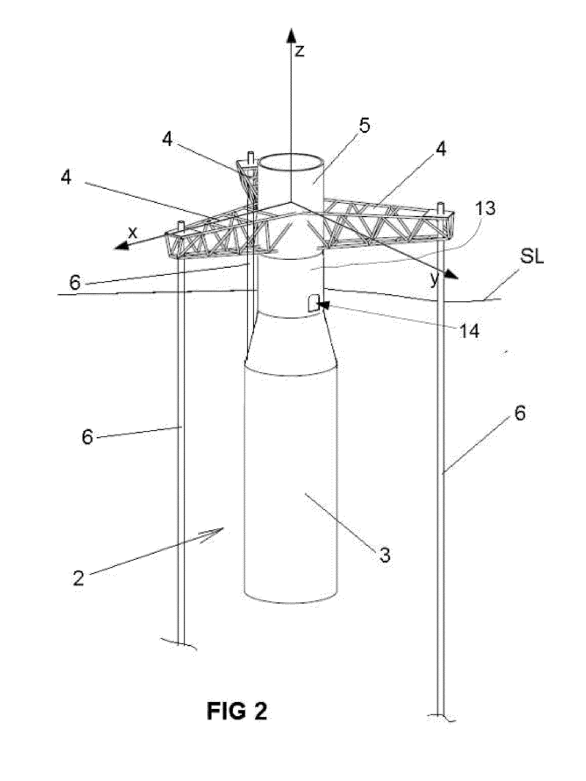
[0029]The wind turbine 1 may comprise a buoyancy structure 2, with at least one floater tank 3. The buoyancy structure 2 may be designed such as to remain submerged in a position above the sea bed SB and below the sea level SL to provide an upward thrust for supporting the weight of the wind turbine 1 and other loads.

[0030]In order to stabilize a floating wind turbine with such a buoyancy structure, i.e. in order to restrain its six degrees of freedom (surge, sway, heave, pitch, roll and yaw) within acceptable limits, mooring lines 6 may be put under tension by the excess buoyancy provided by the float...


PUM


Abstract

A floating offshore structure comprises a buoyancy structure arranged such that in use it remains below the sea level and a tower, wherein the buoyancy structure is attached to a tower by a connecting structure, the connecting structure comprising one or more openings arranged such that in use they remain below the sea level, and the one or more openings being dimensioned such that sea water can flow into and out of the connecting structure with variations of the sea level.

Description

[0001]This application claims the benefit of European Patent Application 13382251.0 filed on Jun. 27, 2013, the entire contents of which are hereby incorporated by reference for all purposes.[0002]The present disclosure relates to floating offshore structures.BACKGROUND ART[0003]Floating offshore structures such as e.g. oil platforms, offshore wind turbines, and offshore meteorological towers are known.[0004]Several configurations have been proposed for the floating or buoyancy of structures: many of these employ floater elements in the form of substantially hollow floater tanks that in use are arranged substantially below the sea level and provide a buoyancy force to support the structure, e.g. a wind turbine. Ballast and / or mooring lines anchored to the seabed are provided for achieving stability.[0005]In some of these floating structures, the buoyancy structure is designed to provide an excess buoyancy force and is maintained floating under the sea level by taut mooring lines ten...

Claims


Application Information

Patent Timeline
Patent Type & Authority Applications(United States)
IPC IPC(8): B63B35/44
CPCB63B2035/446B63B35/44B63B21/50B63B1/107B63B1/048B63B21/502B63B2001/044B63B2035/442Y02E10/727
Inventor BETRAN PALOMAS, JAUMEBERGUA, ROGER
Owner GE RENEWABLE TECH WIND BV
Why Eureka
Try Eureka