Check patentability & draft patents in minutes with Patsnap Eureka AI!

Cache memory arrangement and methods for use in a cache memory system

a cache memory and memory system technology, applied in the direction of memory adressing/allocation/relocation, redundant hardware error correction, instruments, etc., can solve the problems of memory leakage and reduced non-volatile capacity, all new transactions may be suspended, and the time delay between the times

Inactive Publication Date: 2003-10-23
IBM CORP
View PDF11 Cites 227 Cited by
  • Summary
  • Abstract
  • Description
  • Claims
  • Application Information

AI Technical Summary

Problems solved by technology

Inherent in this process is a delay between the times when the data is made non-volatile on the two adapters.
Data present in one adapter and not the other may consume space on the first adapter indefinitely, thus resulting in a memory leak and reduced non-volatile capacity.
However, this approach has the disadvantage that all new transactions may be suspended until this flushing operation completes (to avoid the complexity of managing new transactions in parallel with the flushing operation).
This can result in new transactions being suspended for many minutes, which is unacceptable in a high-availability fault-tolerant system.
Furthermore, customer data is exposed to a single point of failure while this flushing operation is in progress.
Two Read transactions, one before this second reset and one after, would return different data, resulting in a data miscompare.
Using this approach, customer data is still exposed to a single point of failure during this, now slower, flushing operation.
This would not take as long as the first option, but still a significant time.

Method used


Image

  • Cache memory arrangement and methods for use in a cache memory system
  • Cache memory arrangement and methods for use in a cache memory system
  • Cache memory arrangement and methods for use in a cache memory system

Examples


Embodiment Construction

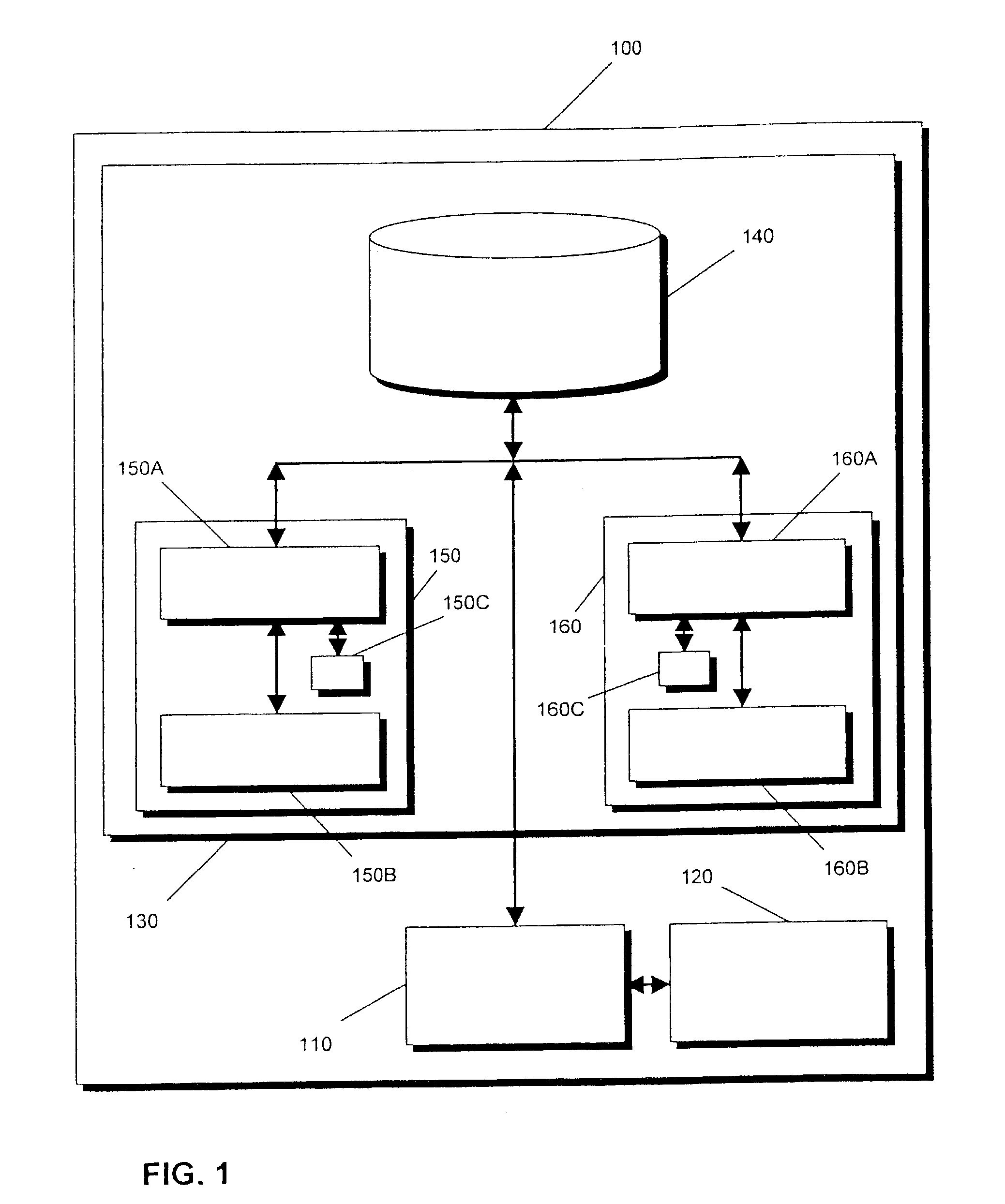
[0029] FIG. 1 is a high level block diagram of a data processing system 100, incorporating one or more processors (shown generally as 110), one or more peripheral modules or devices (shown generally as 120) and a disk storage subsystem 130. The disk storage subsystem 130 includes a disk drive arrangement 140 (which may comprise one or more disk arrays of optical and / or magnetic disks), a first cache adapter 150 and a second cache adapter 160. Each of the cache adaptors 150 and 160 has a dynamic memory (150A and 160A respectively) and a non-volatile memory (150B and 160B respectively). Each adapter also includes a further non-volatile memory 150C, 160C respectively.

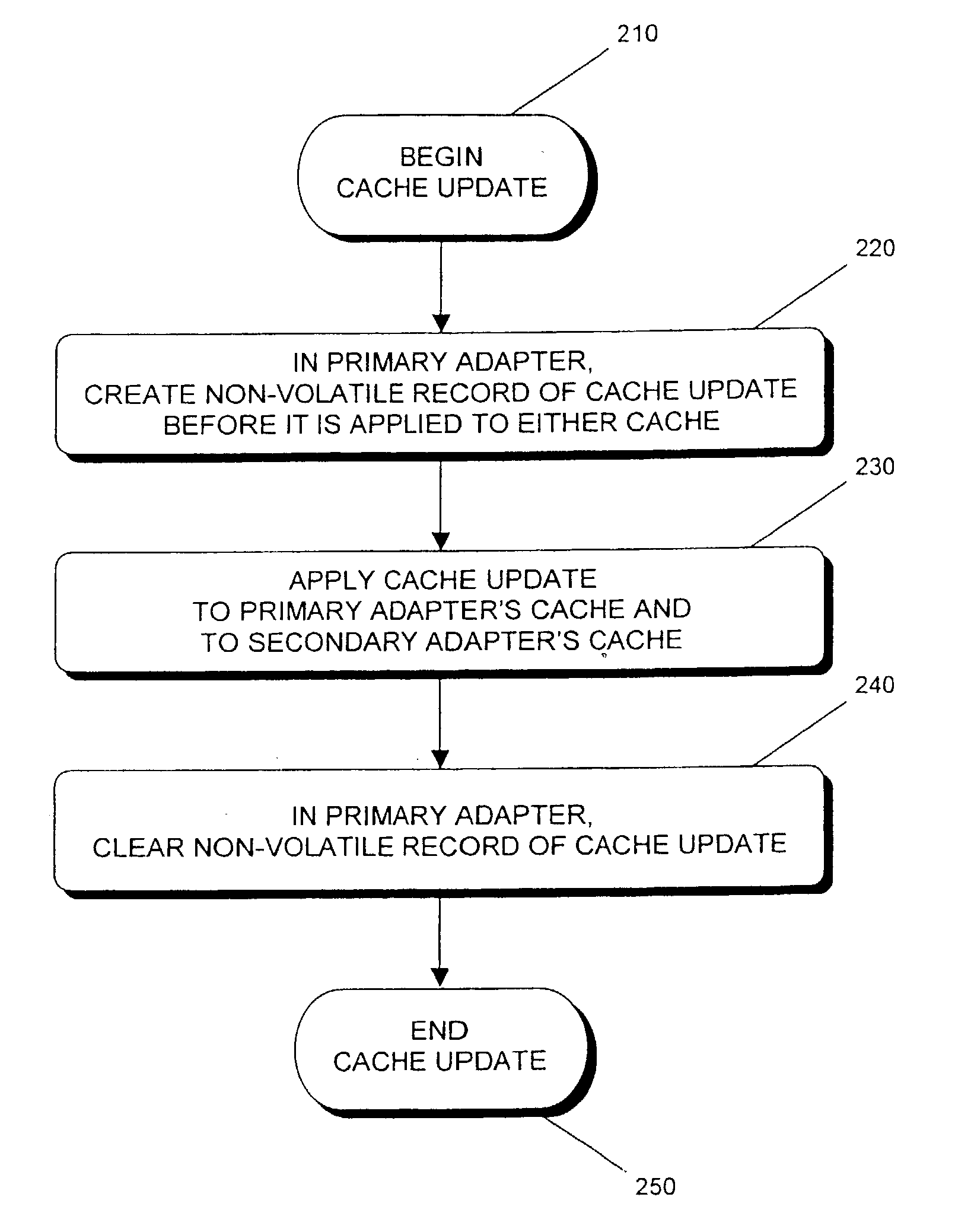
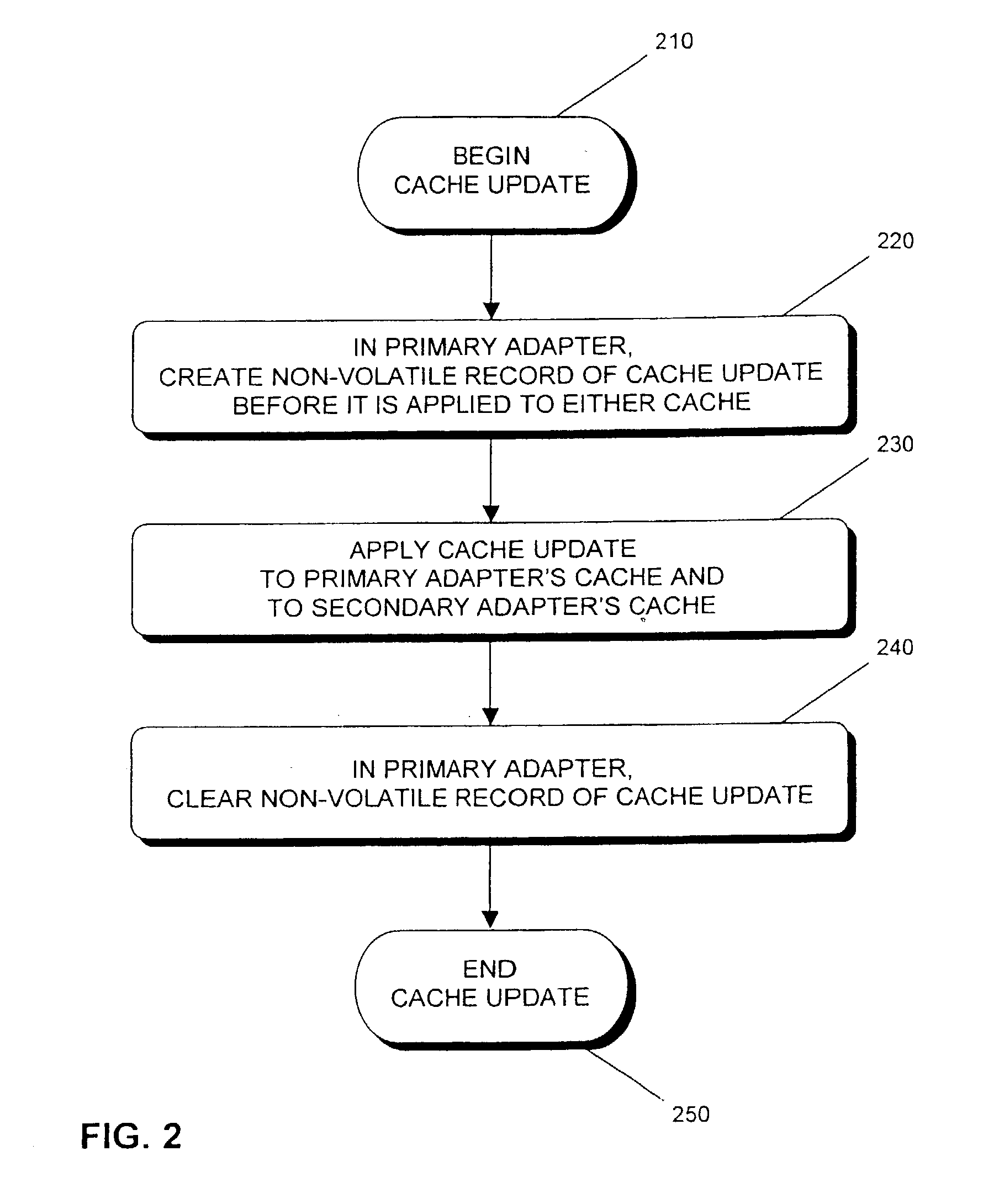
[0030] In use of the system 100, when a write transaction is received on one of the adapters 150 or 160 (the primary adapter) the associated data is transferred to that adapter and stored in non-volatile memory (150B or 160B respectively). This data is also transferred to the other adapter (the secondary adapter) and store...


PUM


Abstract

An arrangement and methods for operation in a cache memory system to facitate re-synchronising non-volatile cache memories (150B, 160B) following interruption in communication. A primary adapter (150) creates a non-volatile record (150C) of each cache update before it is applied to either cache. Each such record is cleared when the primary adapter knows that the cache update has been applied to both adapters' caches. In the event of a reset or other failure, the primary adapter can read the non-volatile list of transfers which were ongoing. For each entry in this list, the primary adapter negotiates with the secondary adapter (160) and transfers only the data which may be different. The amount of data to be transferred between the adapters following reset / failure is generally much lower than under previous solutions, since the data to be transferred represents only the transactions which were in progress at the time of the reset or failure, rather than the entire non-volatile cache contents; also, new transactions need not be suspended while even this reduced resynchronisation takes place: all that is necessary is for the (relatively short) list of in-doubt quanta of data to be searched (if the transaction does not overlap any entries in this list then it need not be suspended; if it does overlap then the transaction may be queued until the resynchronisation completes).

Description

[0001] This invention relates to fault-tolerant computing systems, and particularly to storage networks with write data caching.[0002] In the field of this invention it is known that a storage subsystem may include two (or more) adapters, each with a non-volatile write cache which is used to store data temporarily before it is transferred to a different resource (such as a disk drive).[0003] When a write transaction is received on one adapter (the primary adapter) the associated data is transferred to that adapter and stored in non-volatile memory. This data is also transferred to a second adapter (the secondary adapter) and made non-volatile there too, to provide fault-tolerance. When there is non-volatile data stored in either adapter's cache, the resource is flagged as having data in a cache.[0004] Inherent in this process is a delay between the times when the data is made non-volatile on the two adapters. If a reset or other failure of one or both adapters occurs during this del...

Claims


Application Information

Patent Timeline
IPC IPC(8): G06F11/16G06F11/20G06F12/08G06F12/0866
CPCG06F11/1658G06F2201/82G06F12/0866G06F11/2089
Inventor ASHMORE, PAULFRANCIS, MICHAEL HUWWALSH, SIMON
Owner IBM CORP
Features
  • R&D
  • Intellectual Property
  • Life Sciences
  • Materials
  • Tech Scout
  • Unparalleled Data Quality
  • Higher Quality Content
  • 60% Fewer Hallucinations
Learn More