Re-circulating fluid delivery systems

Inactive Publication Date: 2003-10-30
HEWLETT PACKARD DEV CO LP
View PDF11 Cites 22 Cited by
  • Summary
  • Abstract
  • Description
  • Claims
  • Application Information

AI Technical Summary

Problems solved by technology

Tubes add significant cost to the fluid delivery system, and increase the amount of force required to drive the print head back and forth during printing.
The system can overshoot its operating pressure, or set point, and is therefore at risk for overfilling.
If the cartridge were overfilled, poor print quality or drooling out of the nozzles could result.

Method used


Image

  • Re-circulating fluid delivery systems
  • Re-circulating fluid delivery systems
  • Re-circulating fluid delivery systems

Examples


Embodiment Construction

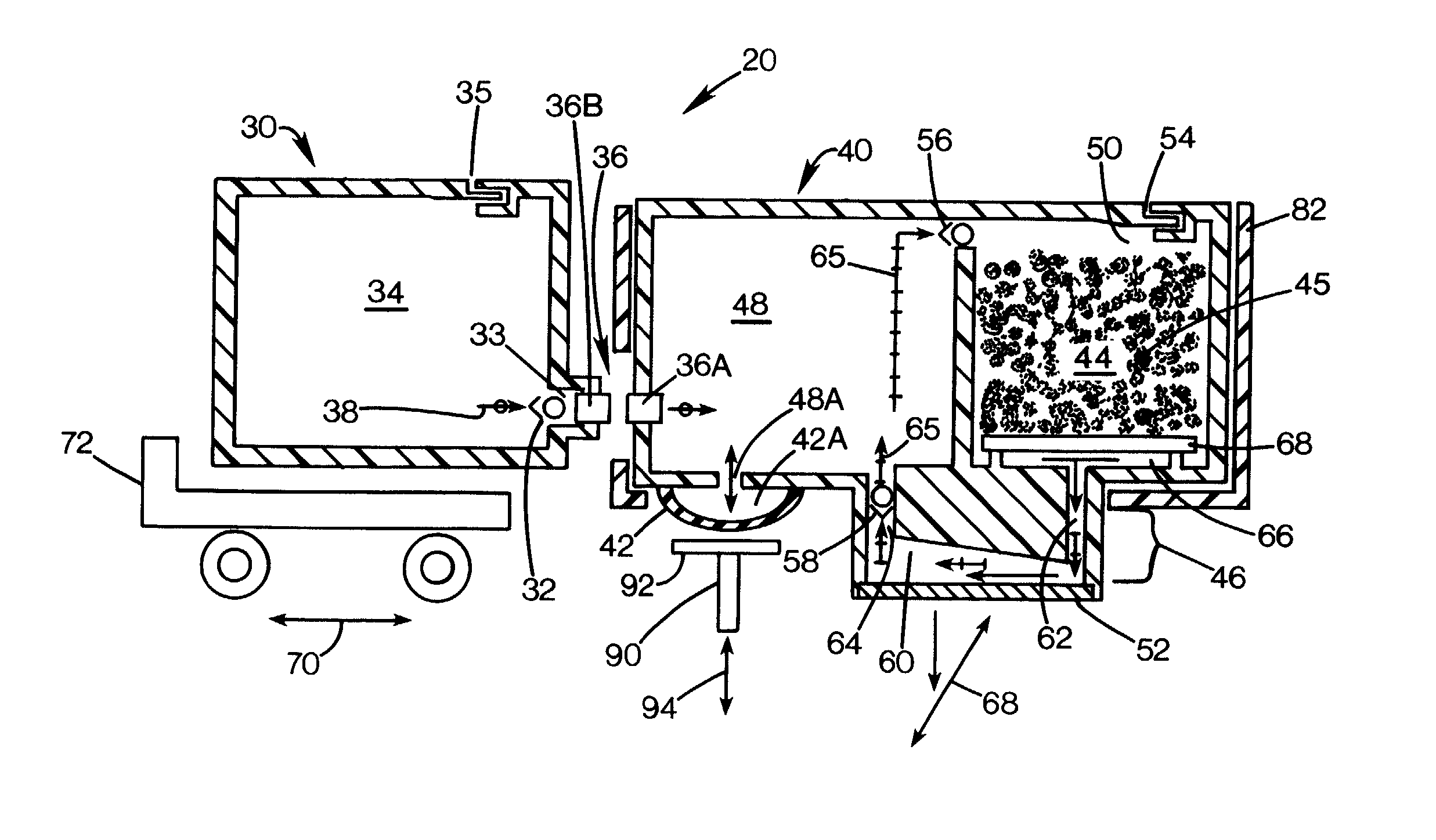
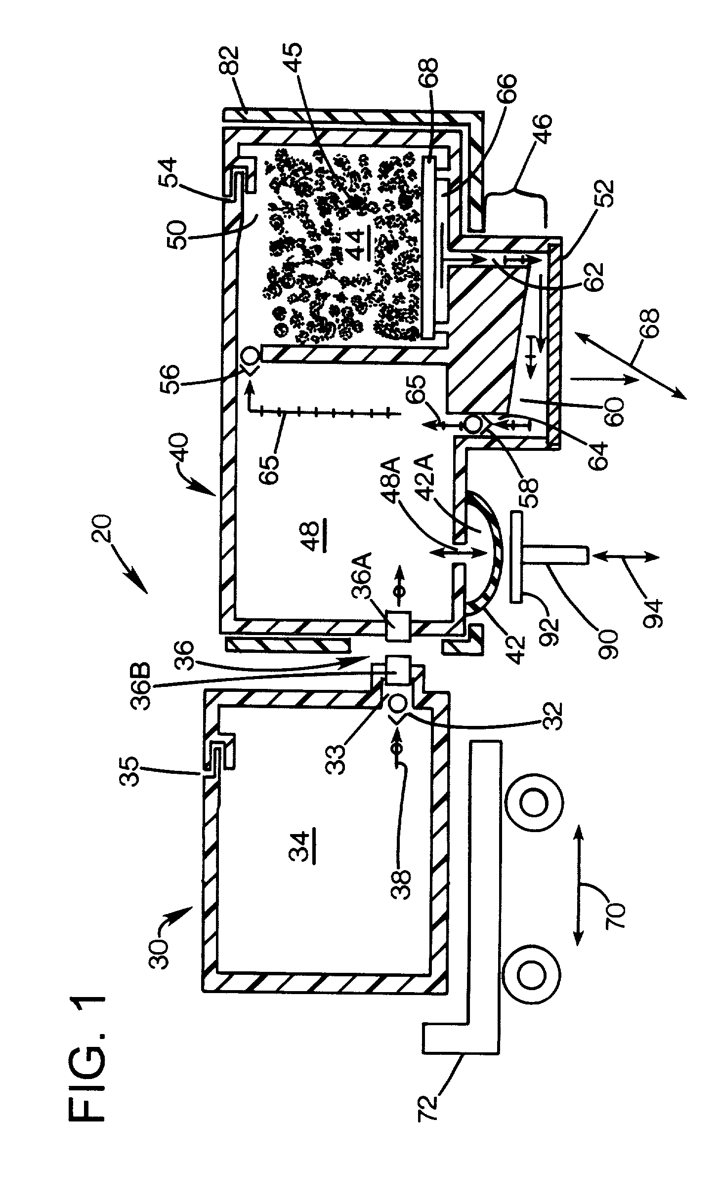
[0011] An exemplary embodiment of a re-circulating fluid delivery system 20 in accordance with aspects of the invention is schematically illustrated in FIG. 1. The system comprises a fluid supply 30, a print cartridge 40 incorporating a pump structure 42 and an air-fluid separator 44. A fluidic interconnect 36 provides a fluid path between the fluid supply and the print cartridge. The air-fluid separator includes a body 45 of some form of capillary material, such as bonded-polyester fiber foam, polyurethane foam or glass beads. In this embodiment, the pump structure 42 is a pump diaphragm that includes an elastomer material formed into a convex shape with an internal spring that rebounds the pump volume after the elastomer is pushed in by an external driving force.

[0012] Exemplary fluid interconnect structures suitable for the purpose as 36A, 36B are known, such as needle-septum interconnects, e.g. as described in U.S. Pat. No. 5,815,182.

[0013] The fluid supply 30 can include a volu...


PUM


Abstract

A re-circulating fluid delivery system includes an air-fluid separator structure, a fluid plenum in fluid communication with the separator structure, and a free fluid reservoir. A fluid re-circulation path fluidically couples the separator structure, the fluid plenum and the free fluid reservoir. A pump structure re-circulates fluid through the re-circulation path during a pump mode, wherein air bubbles may be separated from re-circulated fluid.

Description

BACKGROUND OF THE DISCLOSURE[0001] One exemplary application to which the present invention has utility is that of printing systems. Fluid delivery systems are in common use for delivering liquid ink in printing systems, such as ink-jet printing systems. One type of fluid delivery system is the re-circulating system type. Re-circulating fluid delivery systems are inherently air tolerant. These types of systems move air and ink from the print head region of a print cartridge, separate the air from the ink using either a foam block or by gravity, and circulate the ink back to the print head. The driving force of the re-circulation is generally the same as that to deliver ink.[0002] One type of known re-circulating fluid delivery system employs tubes through which the fluid is delivered. Tubes add significant cost to the fluid delivery system, and increase the amount of force required to drive the print head back and forth during printing. These tube-based systems allow fluid to flow b...

Claims


Application Information

Patent Timeline
IPC IPC(8): B41J2/175B41J2/18B41J2/19
CPCB41J2/175B41J2/17506B41J2/17513B41J2202/12B41J2/17596B41J2/18B41J2/19B41J2/17553
Inventor CHILDS, ASHLEY E.BARINAGA, LOUIS C.DOWELL, DANIEL D.
Owner HEWLETT PACKARD DEV CO LP
Why Eureka
Try Eureka