Cooling and sealing design for a gas turbine combustion system

a technology of combustion system and cooling air supply, which is applied in the direction of machines/engines, stators, light and heating apparatus, etc., can solve the problems of increasing increasing the metal temperature of the combustion liner, and requiring premature replacement, so as to reduce the temperature of the metal, reduce the wear of the seal, and increase the cooling air supply to the interface region

Active Publication Date: 2006-08-29
H2 IP UK LTD
View PDF22 Cites 33 Cited by
  • Summary
  • Abstract
  • Description
  • Claims
  • Application Information

AI Technical Summary

Benefits of technology

[0010]The present invention seeks to overcome the shortcomings of the prior art by providing an interface region between a combustion liner and a transition duct of a gas turbine combustor having improved cooling such that metal temperatures are lowered and component life is increased. These improvements are accomplished by altering various features of the interface region. Specifically, the cooling air supply to the interface region can be increased and the inflow, or re-circulation, of hot combustion gases into the interface region can be minimized. Depending on the desired improvement in cooling efficiency, these adjustments can be combined into multiple embodiments.
[0011]In each embodiment, the transition duct has an inlet ring with a first forward end, a first aft end, and a first plurality of cooling holes proximate the first aft end with the cooling holes directing a cooling fluid, typically air, onto a second aft end of a combustion liner. The combustion liner also includes a second forward end, which receives a plurality of fuel injectors, and at least one outer seal, which is fixed to the combustion liner outer wall at an attachment region that is proximate the second aft end. The combustion liner is telescopically received within the transition duct such that the seal is in contact with the inner wall of the transition duct inlet ring. Dedicated cooling air to the combustion liner aft end is increased in each of the embodiments, and in multiple embodiments, is coupled with a modified liner aft end geometry that results in significantly reduced turbulence and flow re-circulation, leading to lower metal temperatures and increased component life, especially for the seal between the combustion liner and the transition duct.
[0012]It is an object of the present invention to provide an interface region between a combustion liner and a transition duct for a gas turbine combustor having improved cooling and lower metal temperatures.

Problems solved by technology

Poor cooling at the combustion liner aft end results in higher combustion liner metal temperatures and more interference between seal 20 and transition duct 16 due to larger amounts of thermal growth by liner 12 and seal 20.
A greater interference between mating parts results in increased wear to the seal requiring premature replacement.
However, the hot gas flow that has been redirected by deflector 22 tends to adversely affect the heat transfer on the transition duct and first stage turbine vanes and increase their metal temperatures, thereby reducing their component life.

Method used


Image

  • Cooling and sealing design for a gas turbine combustion system
  • Cooling and sealing design for a gas turbine combustion system
  • Cooling and sealing design for a gas turbine combustion system

Examples


Embodiment Construction

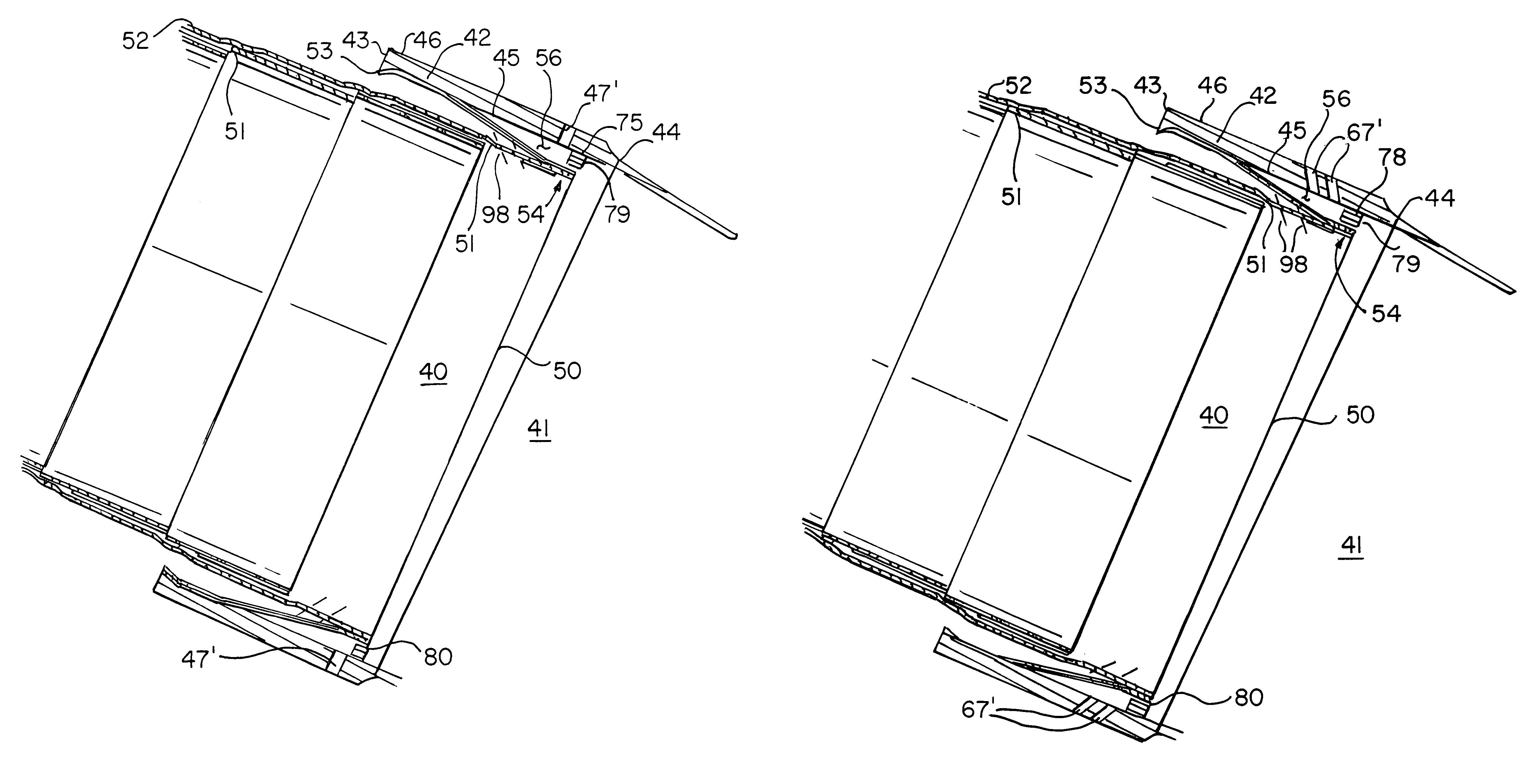
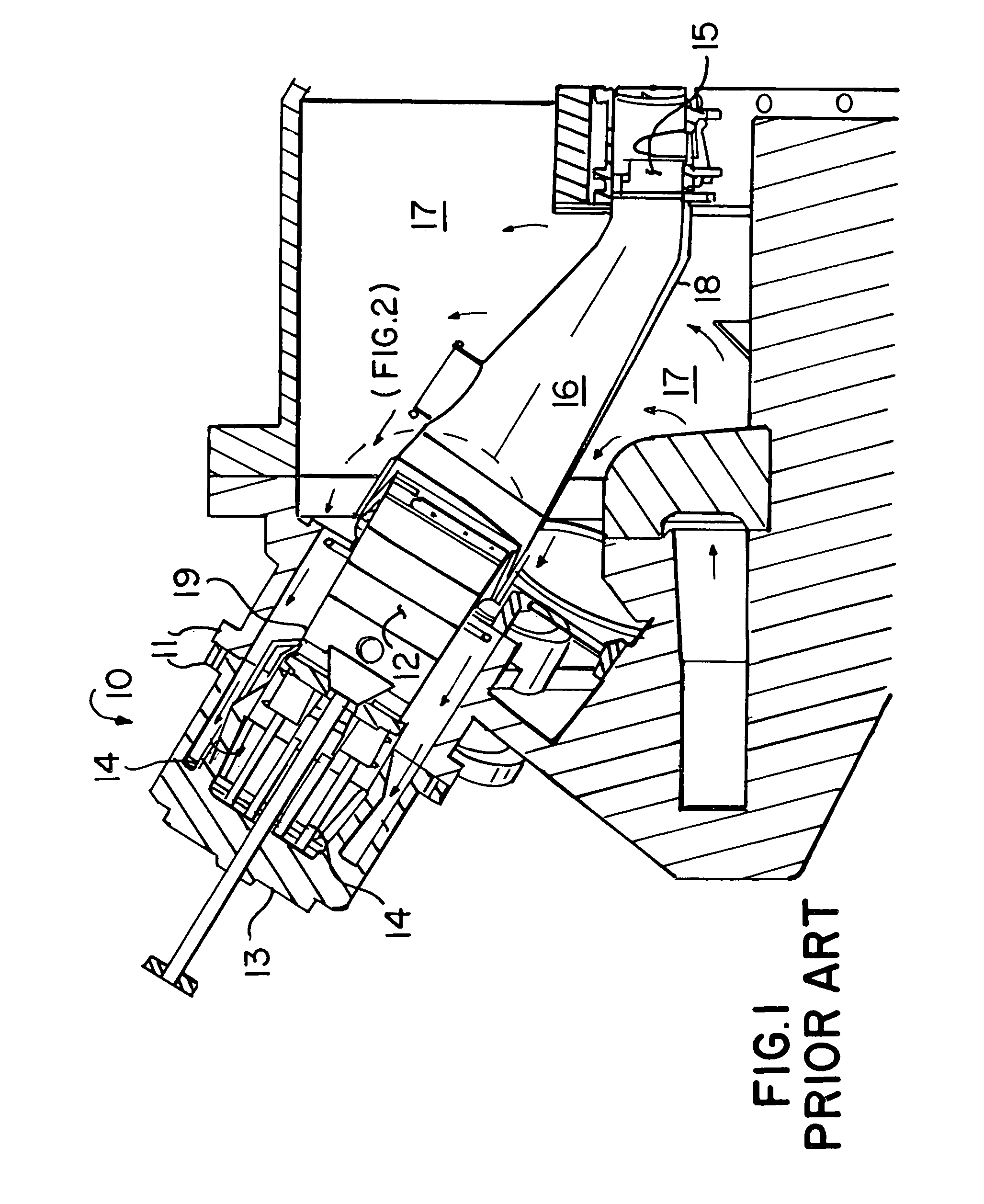
[0023]The present invention is shown in multiple embodiments in FIGS. 3 through 8. The preferred embodiment of the present invention comprises an interface region between a combustion liner 40 and a transition duct 41 having improved cooling. The combustion liner and transition duct disclosed in the preferred embodiment can be used in a combustor similar to that shown in FIG. 1. Transition duct 41 has an inlet ring 42 that has a first forward end 43, a first aft end 44, a first inner wall 45, a first outer wall 46, and a first plurality of cooling holes 47 that extend from first outer wall 46 to first inner wall 45 and are proximate first aft end 44 of inlet ring 42. Inserted telescopically within inlet ring 42 of transition duct 41 is combustion liner 40 having a second forward end with a plurality of receptacles for a plurality of fuel injectors and a second aft end 50 located within inlet ring 42 of transition duct 41. Combustion liner 40 also has a second inner wall 51, a second...


PUM


Abstract

An interface region between a combustion liner and a transition duct of a gas turbine combustor is disclosed having improved cooling such that component life is increased and metal temperatures are lowered. An aft end of a combustion liner is telescopically received within the transition duct such that a combustion liner seal is in contact with an inner wall of the transition duct inlet ring. Increasing the dedicated cooling air supply to the combustion liner aft end, coupled with a modified combustion liner aft end geometry, significantly reduces turbulence and flow re-circulation, thereby resulting in lower metal temperatures and increased component life. Multiple embodiments of the interface region are disclosed depending on the amount of cooling required.

Description

BACKGROUND OF THE INVENTION[0001]1. Field of the Invention[0002]This invention relates to a gas turbine combustor and more specifically to an improved cooling configuration for an interface region between a combustion liner and a transition duct.[0003]2. Description of Related Art[0004]A gas turbine engine typically comprises a multi-stage compressor, which compresses air drawn into the engine to a higher pressure and higher temperature. A majority of this air passes to the combustors, which mixes the compressed heated air with fuel and contains the resulting reaction that generates the hot combustion gases. These gases then pass through a multi-stage turbine, which drives the compressor, before exiting the engine. In land-based gas turbines, the turbine is also coupled to a generator for generating electricity.[0005]For land-based gas turbine engines, often times a plurality of combustors are utilized. Each of the combustion systems include a case that serves as a pressure vessel c...

Claims


Application Information

Patent Timeline
Patent Type & Authority Patents(United States)
IPC IPC(8): F02C1/00F02G3/00F01D9/02F23R3/42F23R3/60
CPCF01D9/023F23R3/60F23D2211/00F23R2900/03041F23R2900/00005F23D2214/00
Inventor MARTLING, VINCENT C.XIAO, ZHENHUA
Owner H2 IP UK LTD
Why Eureka
Try Eureka