Pyrolysis system for waste rubber

a waste rubber and pyrolysis technology, applied in lighting and heating apparatus, production of liquid hydrocarbon mixtures, drying peat, etc., can solve the problems of high cost, high difficulty in accessing, and hazardous storage of large quantities of scrapped waste tires

a waste rubber and pyrolysis technology, applied in lighting and heating apparatus, production of liquid hydrocarbon mixtures, drying peat, etc., can solve the problems of high cost, high difficulty in accessing, and hazardous storage of large quantities of scrapped waste tires

US20090211892A1Inactive Publication Date: 2009-08-27ANDERSEN DAN

Image

  • Pyrolysis system for waste rubber
  • Pyrolysis system for waste rubber
  • Pyrolysis system for waste rubber

Examples


Embodiment Construction

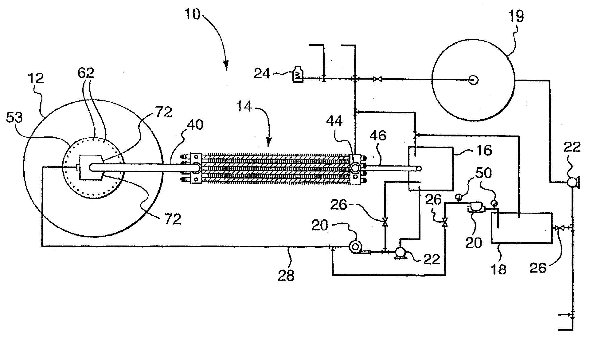
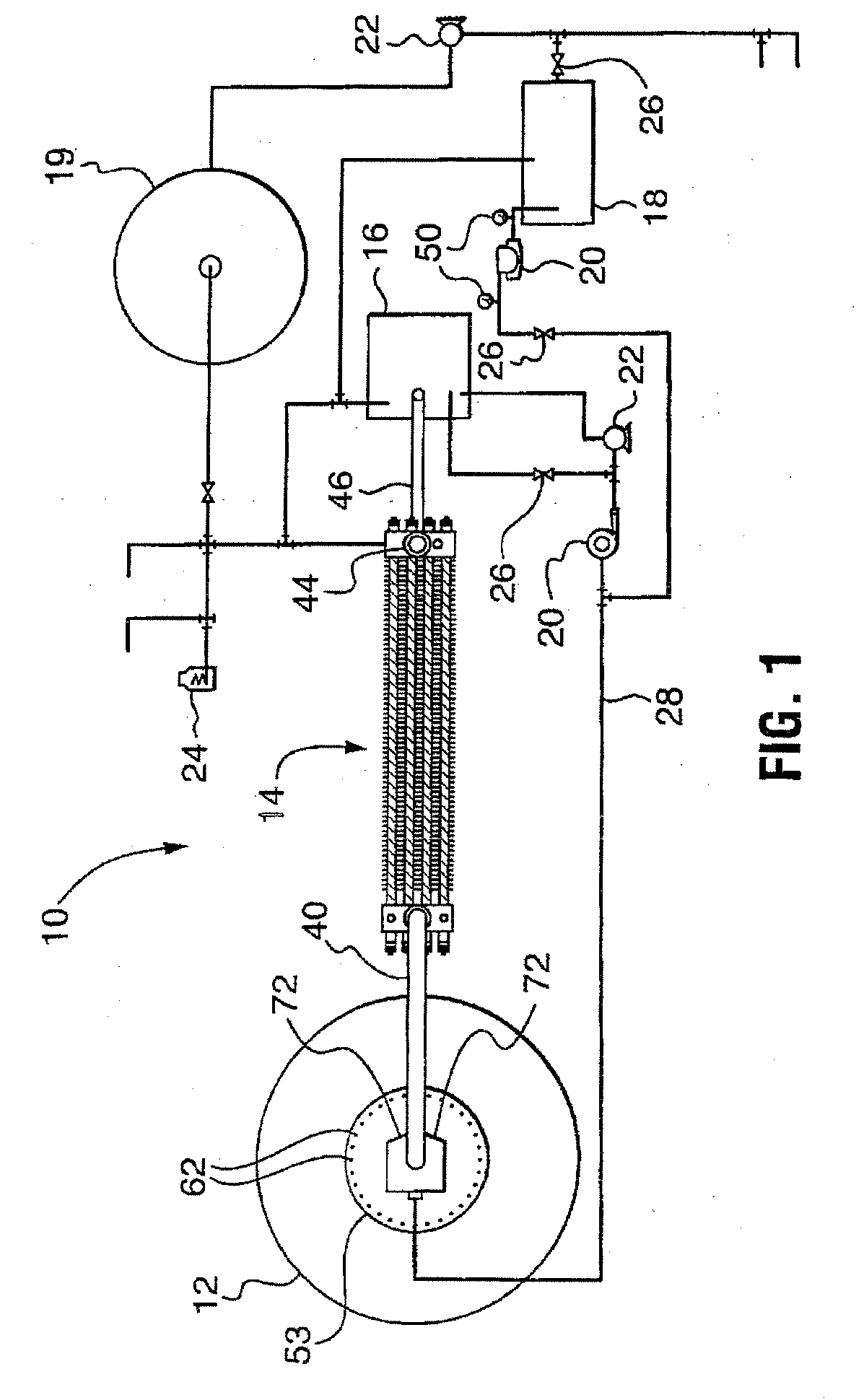
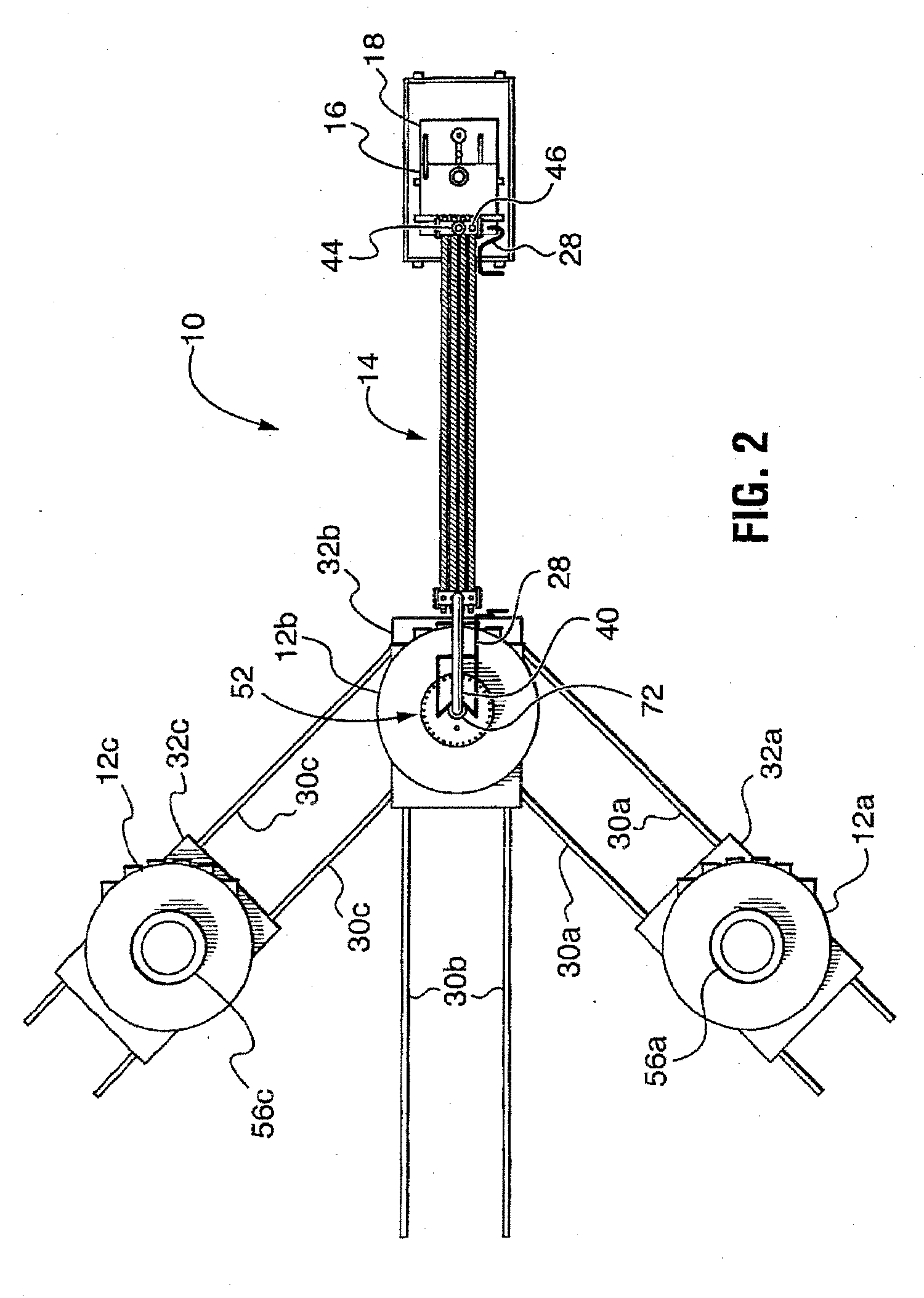
[0039]An exemplary embodiment of the rubber processing apparatus is shown in accompanying drawings, and is generally referred to by the numeral 10. As can best be seen in FIGS. 1-4, the apparatus 10 comprises at least one transportable oven 12 having heating elements 38 arranged therein (as can best be seen in FIG. 6), although other heating element arrangements and configurations are possible within the scope of this invention, including diverse possible element numbers, locations and control means). The oven 12 is mountable on an oven cart 32 (as best shown in FIG. 3). Cart 32 is transportable on a track 30 which enables the oven 12 to be moved into a position within a central waste rubber loading area / by-product receiving / holding area in a processing facility where scrapped used tires and other rubber waste can be loaded into the oven, after which the oven 12 is moved by the cart 32 into a position where the oven 12 can be demountably engaged with an oven lid structure 52 for pyr...


PUM

PropertyMeasurementUnit
angleaaaaaaaaaa
temperatureaaaaaaaaaa

Abstract

An apparatus for separating components of batches of waste rubber by pyrolysis comprises at least one heating chamber interconnected with a condenser by a conduit. The heating oven is provided with a plurality of cooperating heating elements, an inlet for receiving waster rubber, and an outlet for egress of pyrolyzed gaseous components. The condenser condenses and separates cooled liquid components from the gaseous components. Separated gaseous components are exhausted from the condenser. Cooled liquid components are conveyed from the condenser to a re-circulation tank. The conduit is provided with a pair of opposed injectors adjacent the outlet of the heating oven. A re-circulation line interconnects the re-circulation tank with the injectors and is provided with a pressurizing device for injecting cooled liquid components through the injectors into the conduit in the form of intersecting liquid laminar sheets thereby applying a vacuum draw on the egressing pyrolyzed gaseous components.

Description

TECHNICAL FIELD [0001]This invention relates to pyrolysis systems and apparatus. More particularly, the invention relates to pyrolysis systems and apparatus for processing waste rubber.BACKGROUND ART[0002]Disposal of used rubber tires is associated with major municipal, industrial, environmental and regulatory concerns worldwide due to: (1) the non-durable nature and relatively rapid wear properties of rubber tires and other such products, (2) the recalcitrance of rubber-based products in terrestrial and aquatic environments, and (3) the technical difficulties and high costs associated with processing scrapped used rubber tires and other forms of waste rubber. In the United States for example, it is estimated that waste tires are generated at an average rate of one tire per capita annually resulting in the production of over 300 million scrapped used tires. This is equivalent to 5.28 million tons of scrapped used tires each year which represents nearly 2% of the total solid waste ge...

Claims


Application Information

Patent Timeline
27 Aug 2009
Publication
US20090211892A1
IPC
C10B53/07; C10B1/02; B01D5/00; B01D3/00
CPC
B01D5/0003; Y02E20/363; B29B17/02; B29B2017/0496; B29K2021/00; C08J11/10; C08J11/12; C08J2321/00
Inventors
CUNNINGHAM, WILLIAM FREDERICK; SCHROEDER, DAVID