
Cable testing, cable length, and liquid level determination system utilizing a standing wave reflectometer

a technology of standing wave reflectometer and liquid level determination system, which is applied in the direction of machine/engine, line-transmission details, instruments, etc., can solve the problems of limited cable length that can be measured, significant cost and important consequences, and the use of cables in many locations where they are difficult to reach

Inactive Publication Date: 2003-12-04
UTAH STATE UNIVERSITY
View PDF8 Cites 43 Cited by
  • Summary
  • Abstract
  • Description
  • Claims
  • Application Information

AI Technical Summary

Problems solved by technology

Due to the discrete nature of the FFT, the length of cable that can be measured is limited.
Specifically, wire and cable testing is a critically important industry that has significant costs and important consequences.
For example, cables are used in many pieces of equipment that can suffer catastrophic failures and cause injuries.
For example, cables are used in many locations where they are difficult to reach, such as in the infrastructure of buildings and homes.
Essentially, in many cases it is simply not practical to remove cables for testing, especially when this action can cause more damage than it prevents.
One of the main disadvantages of TDR is that the equipment required to perform time analysis of a reflected signal is expensive and often bulky.
Miles of cabling inside a single airplane is extremely difficult to reach and test.
If the cabling is removed for testing, the cabling can be damaged where no damage existed before.
Thus, testing can result in more harm than good when cabling must be moved to gain access.
But the nature of cable carrying conduit in an airplane simply makes access with bulky testing equipment difficult.

Method used

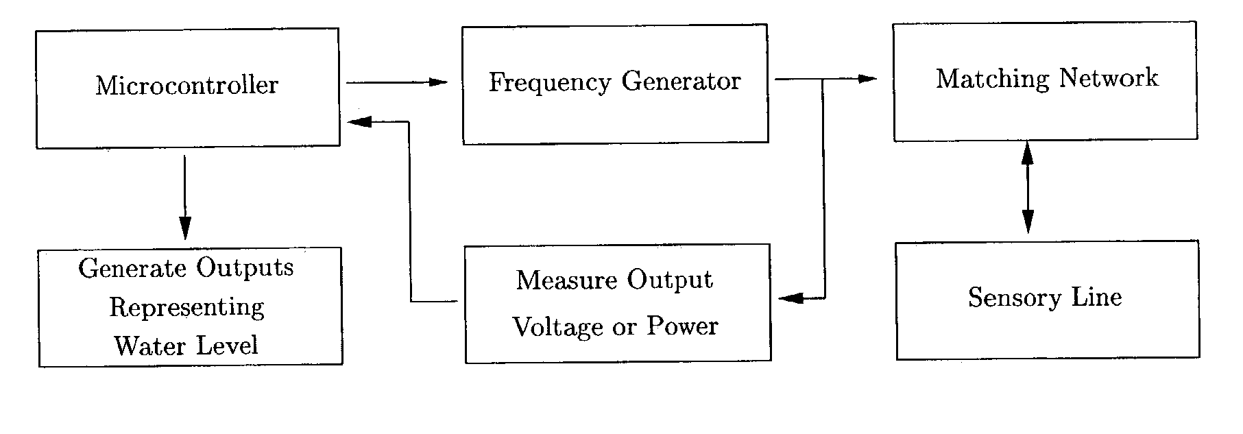
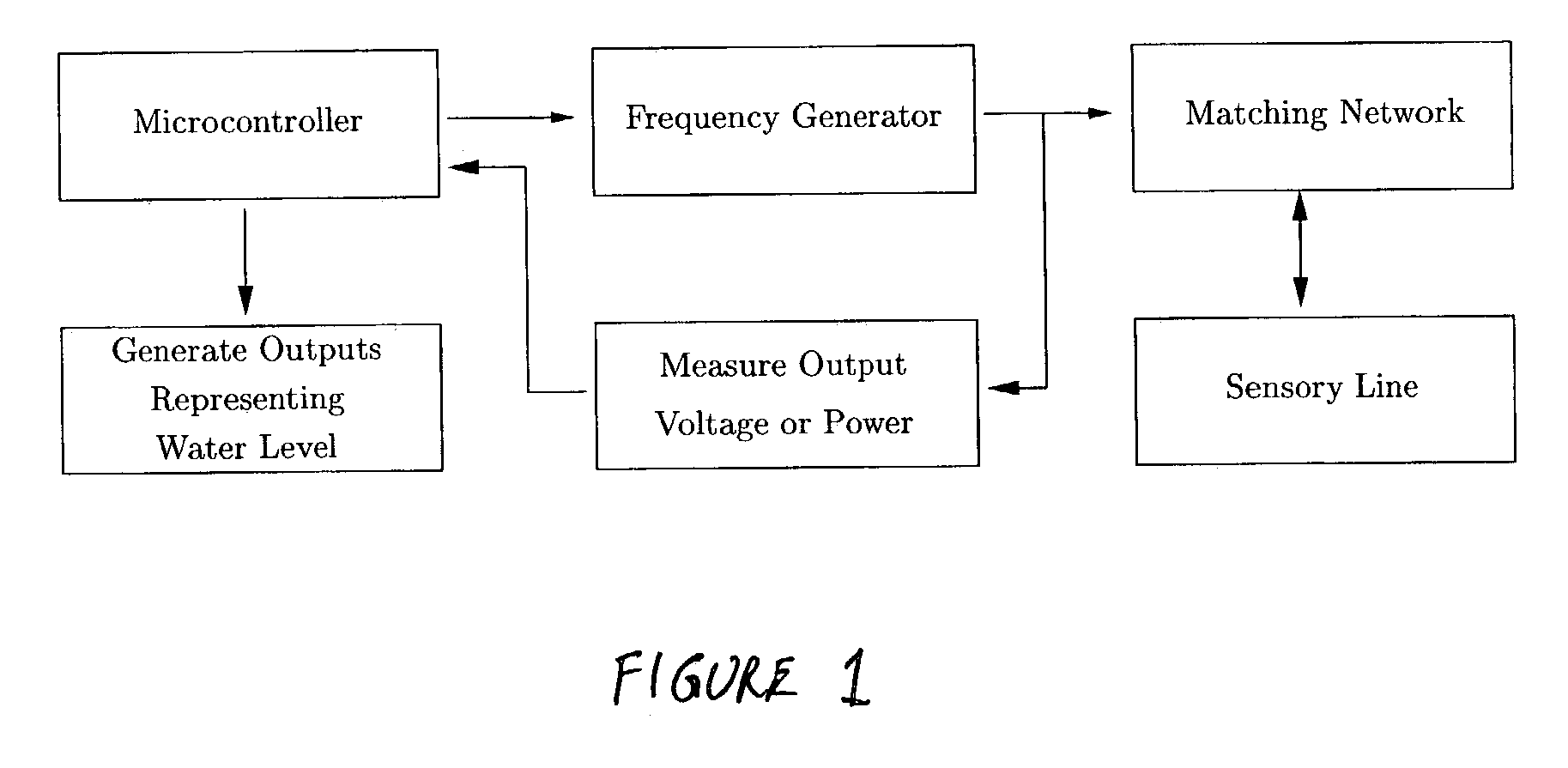
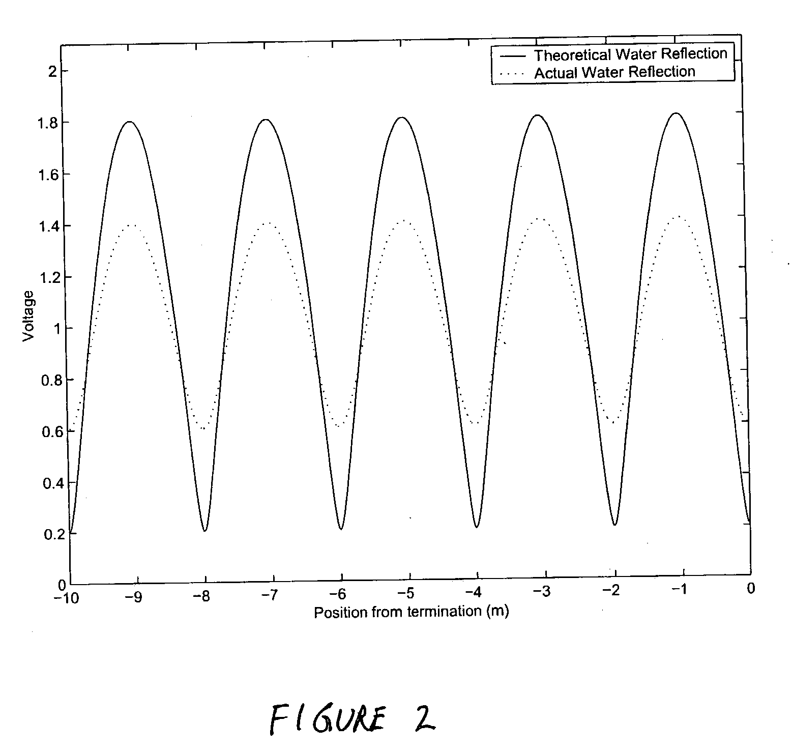

Image

  • Cable testing, cable length, and liquid level determination system utilizing a standing wave reflectometer
  • Cable testing, cable length, and liquid level determination system utilizing a standing wave reflectometer
  • Cable testing, cable length, and liquid level determination system utilizing a standing wave reflectometer

Examples


Embodiment Construction

and sent with this application on two compact disks labeled Copy 1 and Copy 2.

[0135] It is to be understood that the above-described arrangements are only illustrative of the application of the principles of the present invention. Numerous modifications and alternative arrangements may be devised by those skilled in the art without departing from the spirit and scope of the present invention. The appended claims are intended to cover such modifications and arrangements.


PUM


Abstract

A standing wave reflectometer (SWR) that generates a standing wave on a conductor, receives a reflected standing wave, converts the reflected standing wave to a digital representation, determines a plurality of curve fitted minima of the digital representation of the reflected standing wave, and determines a location along the conductor where there is an interruption in uniformity such as at the end of the conductor, or where the conductor is touching a liquid, and thereby determine integrity of the conductor, length of the conductor, or a level of the liquid.

Description

[0001] This document is a continuation of, claims priority to, and incorporates by reference all of the subject matter included in the provisional patent application filed on Nov. 30, 2001, and having serial No. 60 / 335,280.[0002] 1. Field of the Invention[0003] This invention relates generally to the use of Standing Wave Reflectometers (SWR) to determine where a signal is reflected along a length of a conductor. More specifically, the invention relates to determining a length of a wire or cable (a conductor) or a level of a liquid by determining where along a length of the conductor that a signal is reflected, wherein reflection is a result of the signal coming to the end of the conductor, or the result of the conductor touching a liquid causing a discontinuity in impedance, wherein the invention utilizes the principles of SWR to analyze the reflected signal, and wherein the system also enables cable testing by applying the same SWR principles.[0004] 2. Description of Related Art[00...

Claims


Application Information

Patent Timeline
IPC IPC(8): G01F23/00G01F23/28G01F23/284G01R31/11H04B3/46
CPCG01F23/0069G01F23/28H04B3/46G01R31/11G01F23/284G01F23/802
Inventor FURSE, CYNTHIA M.WOODWARD, RAYMOND J.
Owner UTAH STATE UNIVERSITY
Features
  • Generate Ideas
  • Intellectual Property
  • Life Sciences
  • Materials
  • Tech Scout
  • Unparalleled Data Quality
  • Higher Quality Content
  • 60% Fewer Hallucinations
Learn More