Manhole debris-catching system

a technology of debris catching and manhole, which is applied in the direction of artificial islands, sewer cleaning, separation processes, etc., can solve the problems of expensive excavation, exposing the pipe, and requiring expensive excavation or vacuuming

Inactive Publication Date: 2004-01-15
PETERSEN JOHN G +1
View PDF8 Cites 12 Cited by
  • Summary
  • Abstract
  • Description
  • Claims
  • Application Information

AI Technical Summary

Benefits of technology

The technical effect of this patent is that it provides a way to prevent dirt and other objects from getting into the sewer system through a hole called a manhole.

Problems solved by technology

The technical problem addressed in this patent text needs to be identified by a senior R&D personnel.

Method used


Image

  • Manhole debris-catching system
  • Manhole debris-catching system
  • Manhole debris-catching system

Examples


Embodiment Construction

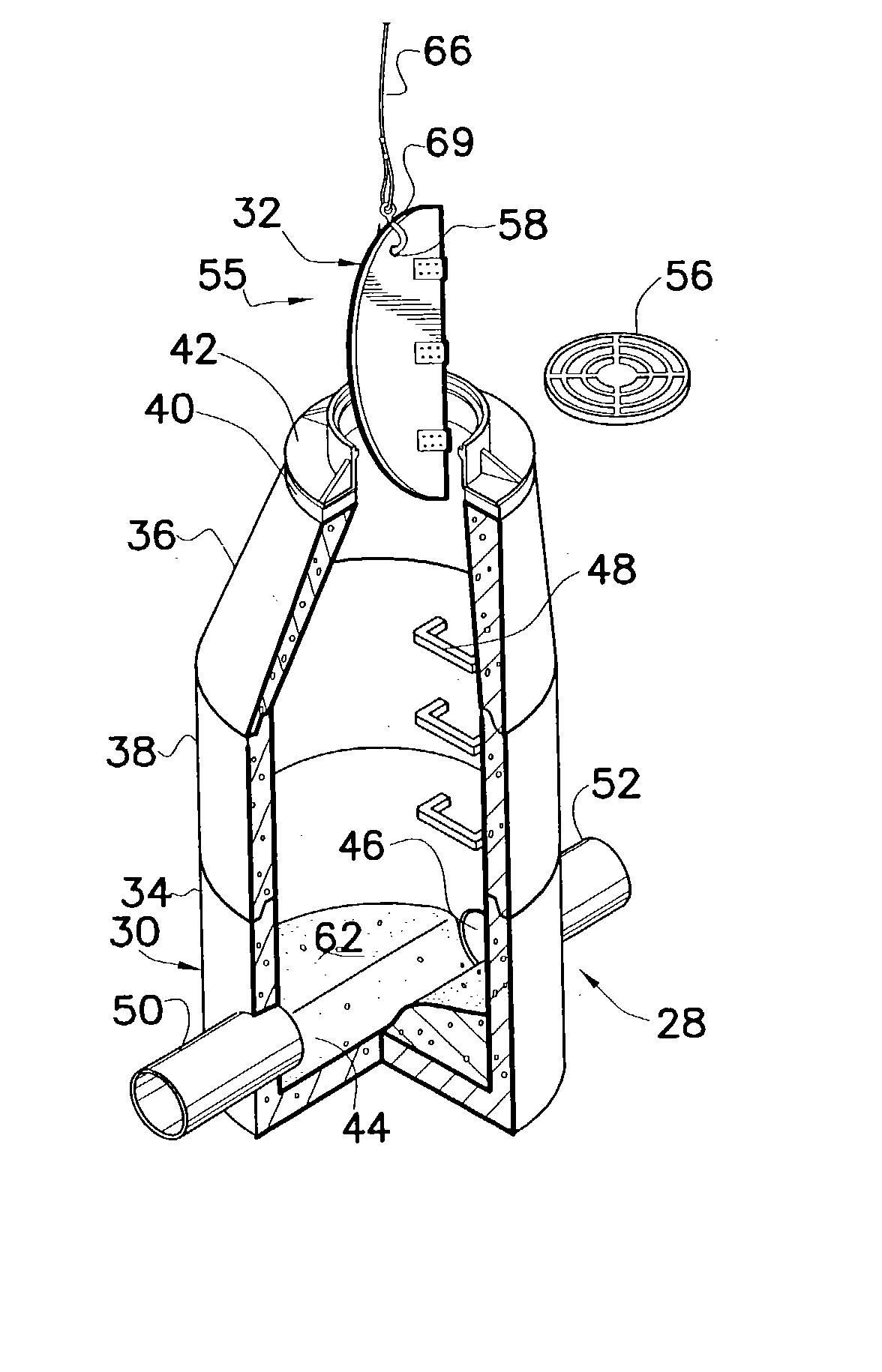
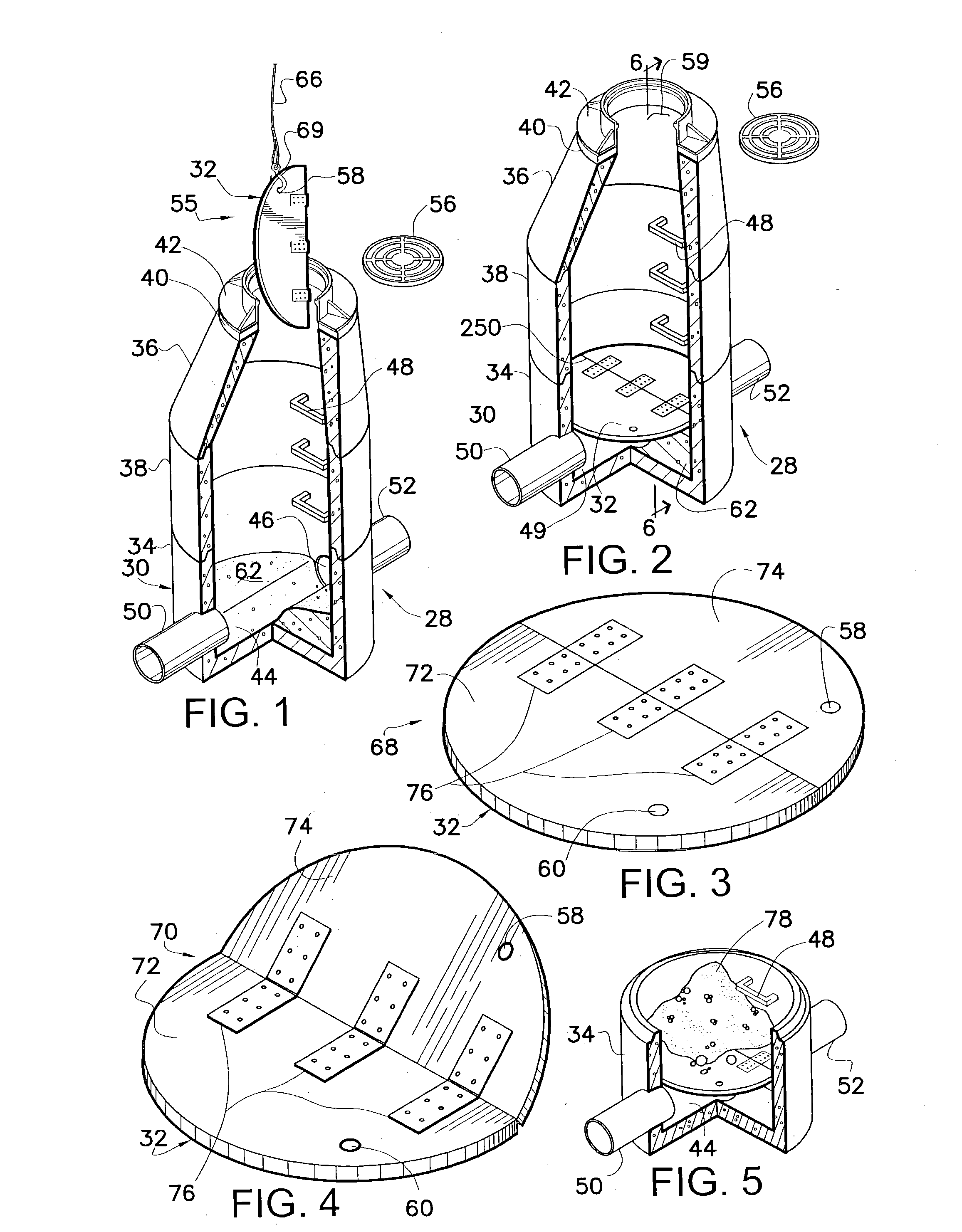
[0049] Reference is now made to the drawings. FIG. 1 is a perspective view, partially in section, of a typical manhole structure 30 illustrating the debris-catching system 28 and insertion of a debris-catcher 32 (embodying herein substantially-rigid blocker means, supportable by the flat bottom portions and larger than the round top, for blocking debris from entering the pipe trench portions; and also embodying herein a substantially-rigid blocker, supportable by the flat bottom portions and larger than the round top, structured and arranged, when not folded and when supported by the flat bottom portions, to block debris from entering the pipe trench portions), according to a preferred embodiment of the present invention. A typical manhole structure 30 comprises a lower portion 34, a top portion 36, and may comprise one or more center portions 38. The center portions 38 assist in adjusting the manhole structure 30 to the approximate desired height. In addition, the top portion 36 ma...


PUM

PropertyMeasurementUnit
Diameteraaaaaaaaaa
Diameteraaaaaaaaaa
Diameteraaaaaaaaaa

Abstract

A debris-catching system for preventing debris from falling into the pipe opening at the bottom of a manhole catch basin. The debris-catcher comprises two semi-circular halves hinged together such that the two halves may be folded and inserted into a manhole opening. The debris-catcher comprises aligned apertures that allow it to be hooked and lowered into a manhole. The two halves are opened up to form a circular blocker which sets on the manhole bottom flat base. The debris-catcher allows normal effluent flow through the manhole while in place. The debris-catcher floats and will do so during an overflow condition. Further, the debris-catcher will resume its protective function after an overflow condition has subsided.

Description


Claims


Application Information

Patent Timeline
Owner PETERSEN JOHN G
Why Eureka
Try Eureka