Electric junction box template

a junction box and template technology, applied in the field of templates, can solve the problems of paper templates not having an edge that is easily traced, unstable or accurate templates when held,

Inactive Publication Date: 2004-03-04
HALL MATTHEW R
View PDF13 Cites 14 Cited by
  • Summary
  • Abstract
  • Description
  • Claims
  • Application Information

AI Technical Summary

Problems solved by technology

However, these templates are not stable or accurate when held to the surface and are useful for a limited number of installations.
In addition, the paper templates do not have an edge that is easily traced.

Method used


Image

  • Electric junction box template
  • Electric junction box template
  • Electric junction box template

Examples


first embodiment

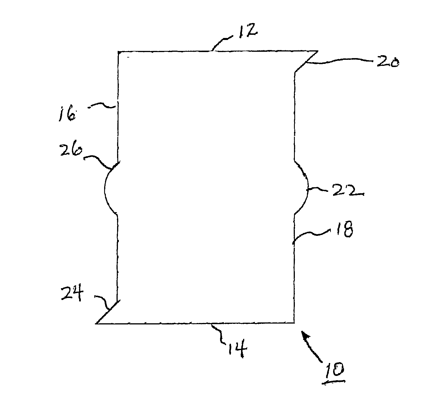
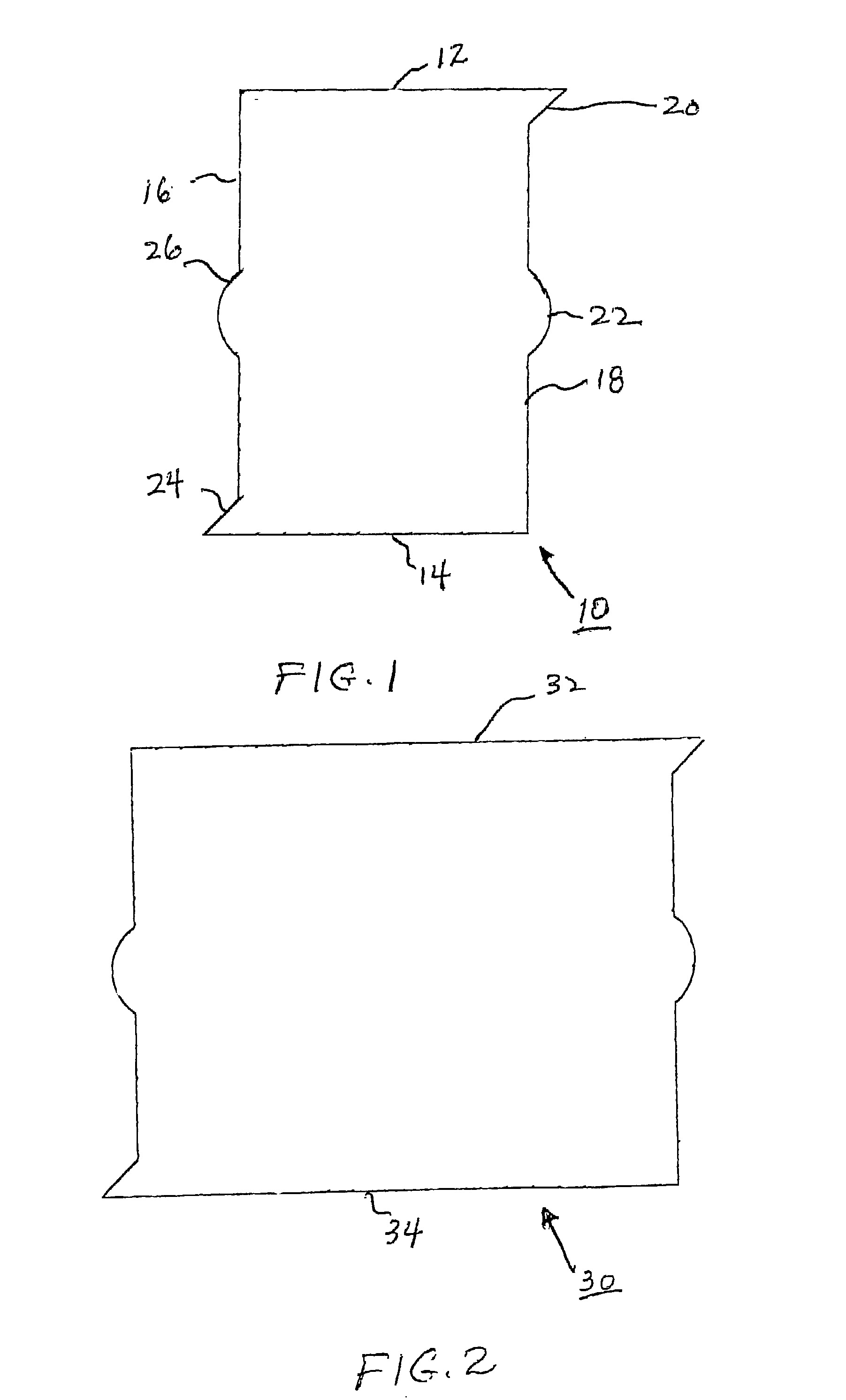
[0018] FIG. 1 illustrates the present invention wherein a template 10 is illustrated. Template 10 is a rectangular in shape having top 12, bottom 14, left 16, and right 18 edges. The top edge extends in a first horizontal direction, the right edge has a triangular protrusion 20 at the top, an arc protrusion 22 midway along the right edge 18, the remainder of edge 18 being straight. The bottom edge 14 is straight and the left edge 16 has a triangular protrusion 24 at the bottom, an arc protrusion 26 midway along the left edge 16, the remainder of the edge 16 being straight. Template 10 (and the other templates shown in the drawings) is preferably made of a thin plastic material (although other materials can be used) and has a thickness, typically 1 / 8 inch, to provide an edge for a marking device, such as a pencil, to trace an outline around the edges.

second embodiment

[0019] FIG. 2 illustrates the present invention wherein a template 30 is illustrated. Template 30 is identical to the template shown in FIG. 1 with the exception that the length of the top edge 32 and bottom edge 34 is greater.

third embodiment

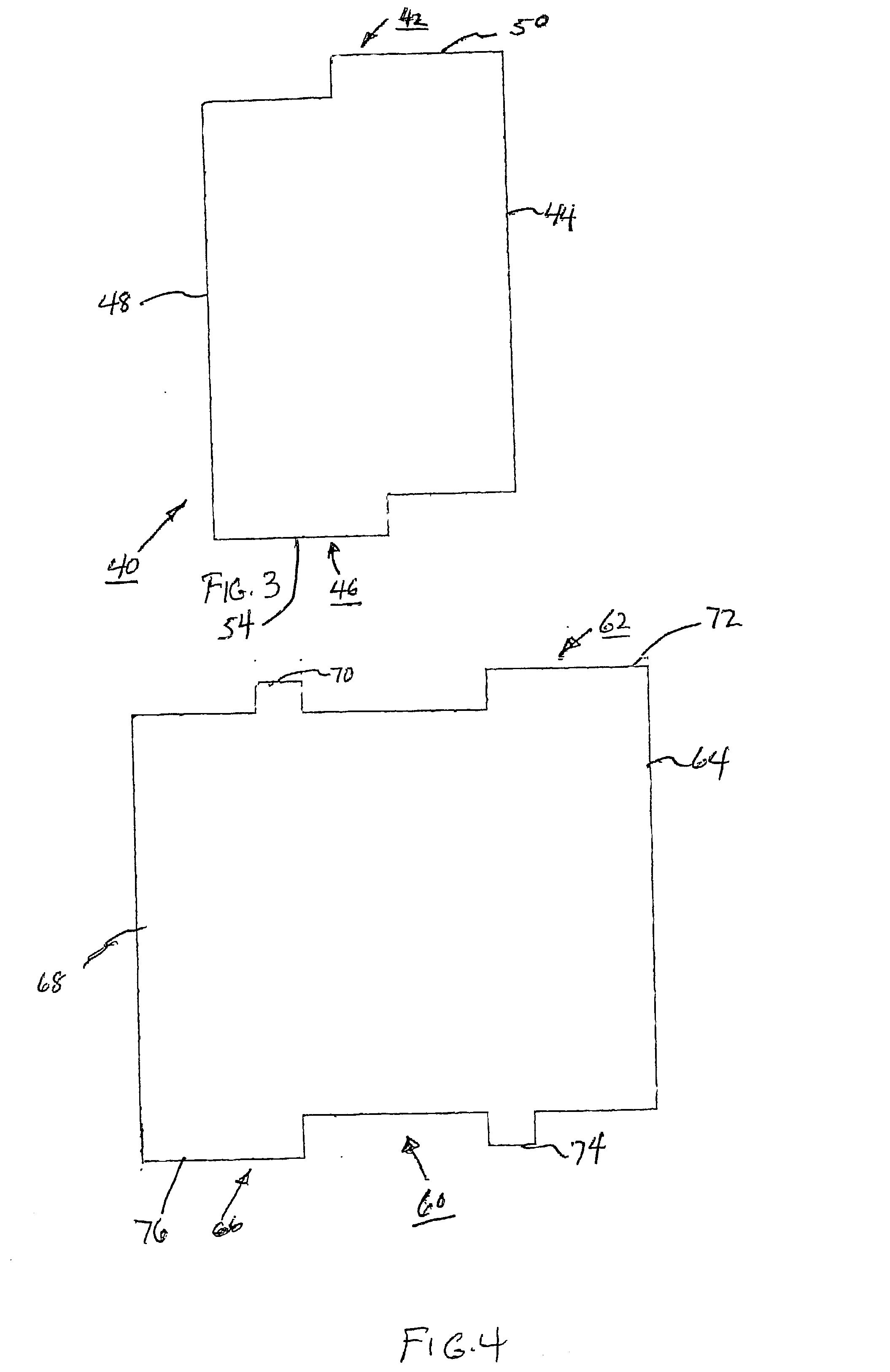
[0020] FIG. 3 illustrates present invention wherein a template 40 is illustrated. Template 40 is rectangular in shape having top, bottom, and left and right edges 42, 44, 46 and 48, respectively. The top edge 42 and bottom edge 46 are shorter than the right edge 44 and left edge 48, the top edge 42 being straight with a step 50 at the right portion as illustrated. The right edge 44 is straight; the bottom edge 46 is straight with a step down 54 on the left portion of the bottom edge 46; the left edge 48 is straight.


PUM


Abstract

A series of templates having a predetermined shape, the combination of shapes corresponding to the shape of most of the commercially available electrical junction boxes. A selected template is positioned on a surface, temporarily secured to the surface, and an outline along the edges of the template then being formed on the surface. A cutout is formed along the outline on the surface and the cut part removed. The electrical junction box is then secured within the opening formed by the cutout.

Description

[0001] 1. Field of the Invention[0002] The present invention relates to a template to provide a level and traceable pattern for the proper placement of a junction box on a surface, the template having means for releasably securing the template to the surface.[0003] 2. Description of the Prior Art[0004] During a remodeling, electricians are required to mark the appropriate place on sheetrock or other wall materials where junction boxes (referred to in the industry as "old work" junction boxes; for reasons of simplicity, the term "junction boxes" will be used hereinafter) will be located and to cut out the marked area. When measuring for the cutout sections in walls, the electrician in practice has utilized a tape measure to measure the appropriate height of the cut-out, and a junction box to trace the shape to be cut out. A ruler has also been used to trace the cut-out shape.[0005] Due to the time constraints and high cost of labor involved inconstruction projects, there is a great n...

Claims


Application Information

Patent Timeline
IPC IPC(8): H02G1/00
CPCH02G2200/30H02G1/00
Inventor HALL, MATTHEW R.
Owner HALL MATTHEW R
Why Eureka
Try Eureka