
Modular transportable floor decking system

Inactive Publication Date: 2004-03-18
GUY FORTIER
View PDF13 Cites 20 Cited by
  • Summary
  • Abstract
  • Description
  • Claims
  • Application Information

AI Technical Summary

Benefits of technology

0013] FIG. 5 is a fragmented side view showing the clamping shoe in abutment with a stopper secured to the inner wall of a longitudinal connecting channel;

Problems solved by technology

However, these systems have been conceived for very large structures for supporting heavy loads such as vehicles.

Method used


Image

  • Modular transportable floor decking system
  • Modular transportable floor decking system
  • Modular transportable floor decking system

Examples


Embodiment Construction

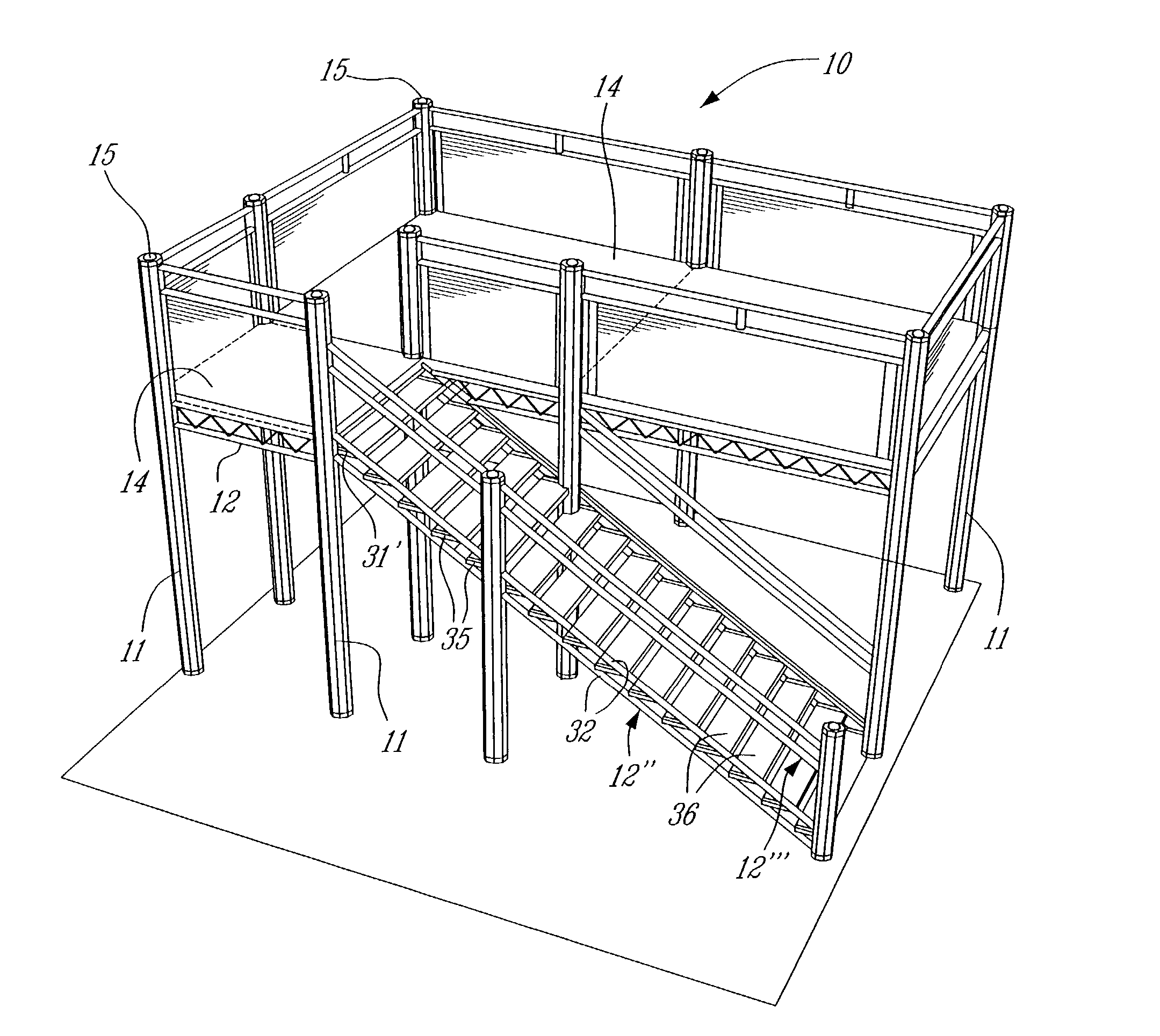
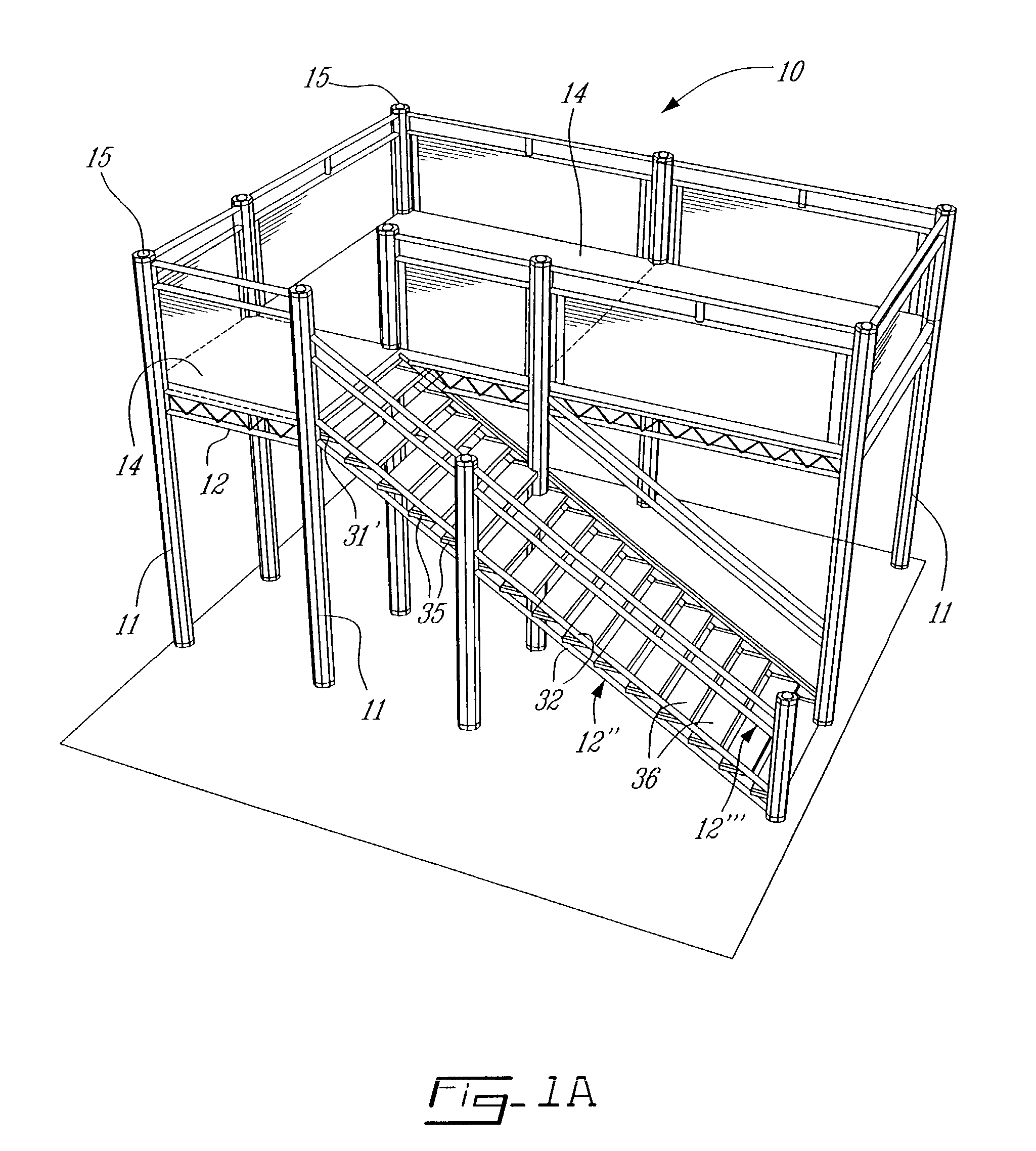
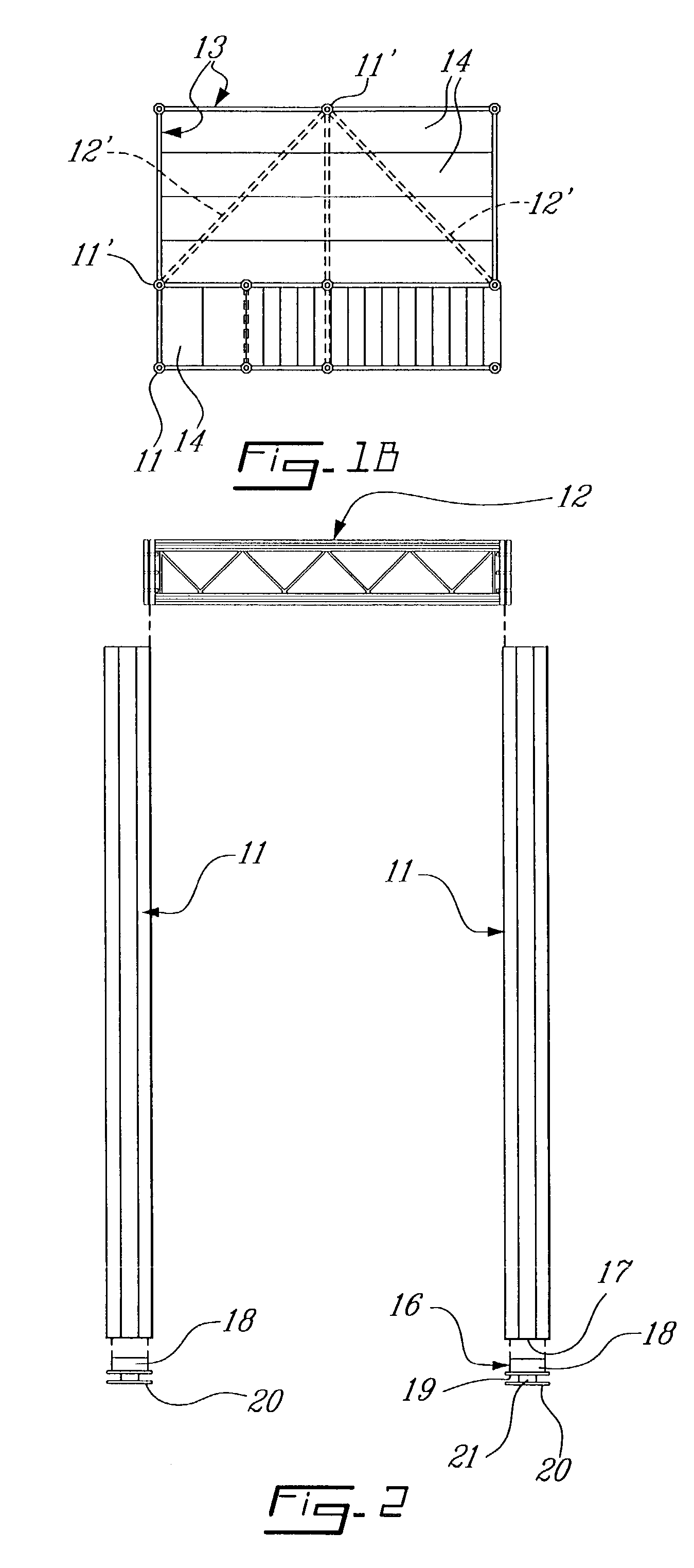
[0016] Referring to the drawings and more particularly to FIGS. 1A and 1B there is shown generally at 10 a modular portable floor decking system constructed in accordance with the present invention for the construction of temporary or permanent flooring structures. The system essentially comprises a plurality of extruded metal hollow support posts 11 and a plurality of beams 12 interconnected to and between the posts 11 whereby to form a support frame 13 which is better illustrated in the simplified top view in FIG. 1B. As hereinshown the beams 12 are connected to the posts 11 at right angle whereby to form a rectangular structure. The beams 12' are also connected diagonally between posts such as posts 11' to span under decking panels 14 to provide support for the flooring structure and to provide structural integrity of the support frame 13.

[0017] The posts 11 are further provided with end caps 15 to conceal the open end of the posts which are extruded aluminum posts as will be des...


PUM


Abstract

A modular portable floor decking system for constructing a temporary or a permanent flooring structure is described. The system comprises a plurality of extruded metal hollow support posts and a plurality of beams interconnectable with the posts to form a support frame. Decking boards are securable across the beams. The support posts each have flat outer surfaces and two or more longitudinal connecting channels each disposed internally of an associated one of the flat outer surfaces. The channels have a central narrow slot extending along the respective flat outer surfaces. The beams have opposed flat connecting end walls and a metal clamping shoe is connected to the end walls of the beams by fasteners whereby to displace the shoe away from the flat surfaces to slide the shoe in a respective connecting channel of the posts as the beam is lowered between two posts. The shoes are clamped in the channels by the use of fasteners which are accessible behind the flat connecting end walls of the beams whereby to clamp the beam between a pair of posts.

Description

[0001] The present invention relates to a modular transportable floor decking system for constructing a temporary or a permanent flooring structure.[0002] Modular portable floor-decking systems are used for constructing elevated platforms at different heights and providing ramps for access thereto. An example of such systems is described in U.S. Pat. Nos. 5,720,135 and 5,848,501. However, these systems have been conceived for very large structures for supporting heavy loads such as vehicles. There is however a need to provide a portable floor decking system which is structurally sound, which is easy to transport and which can be assembled and disassembled quickly by only a few people. There is also a need to provide such a system which does not require any heavy machinery for its loading and unloading from a transport vehicle. There is also a need to provide such a system which is aesthetically pleasing and versatile to construct floor decking systems of different shapes using the s...

Claims


Application Information

Patent Timeline
Patent Type & Authority Applications(United States)
IPC IPC(8): E04B1/00E04B1/24E04F11/02E04H3/28
CPCE04B1/003E04B2001/2454E04H3/28E04F11/02E04B2001/2475
Inventor FORTIER, GUY
Owner GUY FORTIER
Learn More