
Fuel injection valve

Inactive Publication Date: 2004-04-15
ROBERT BOSCH GMBH
View PDF5 Cites 8 Cited by
  • Summary
  • Abstract
  • Description
  • Claims
  • Application Information

AI Technical Summary

Problems solved by technology

In the known fuel injection valve, it is disadvantageous that both the inlet throttle and the outlet throttle must be produced with very high precision in the same component.
Since the inlet conduit and the outlet conduit feed into the control pressure chamber approximately perpendicular to each other, the precise production of the inlet throttle and outlet throttle in the same valve piece is also expensive and the number of manufacturing rejects is correspondingly high.
This is disadvantageous in that the bore let into the valve body for the inlet conduit produces a critical bore error in the vicinity of the pressure bore, which can lead to functional impairments when there are high pressures in the inlet conduit.

Method used


Image

  • Fuel injection valve
  • Fuel injection valve
  • Fuel injection valve

Examples


Embodiment Construction

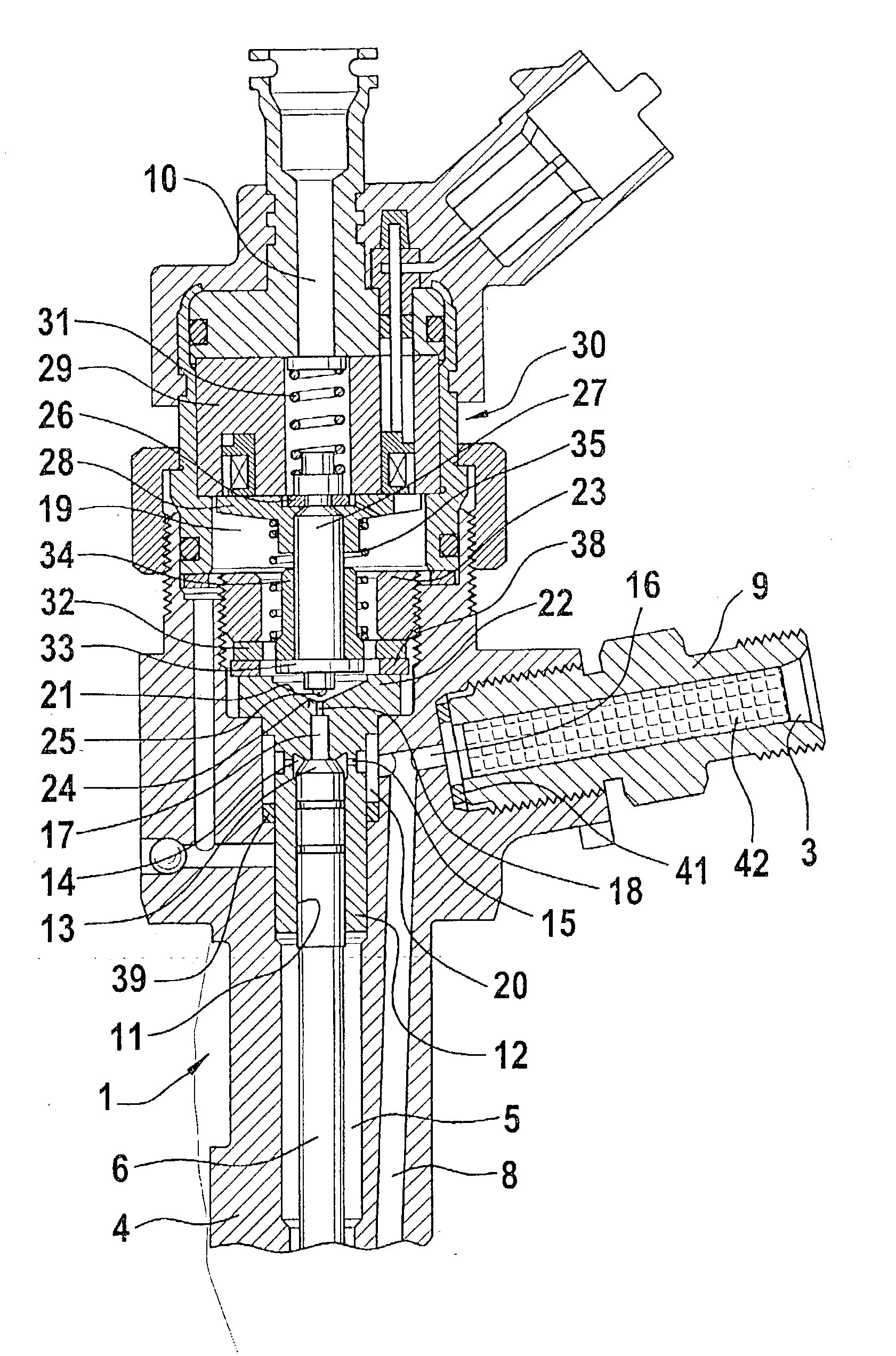
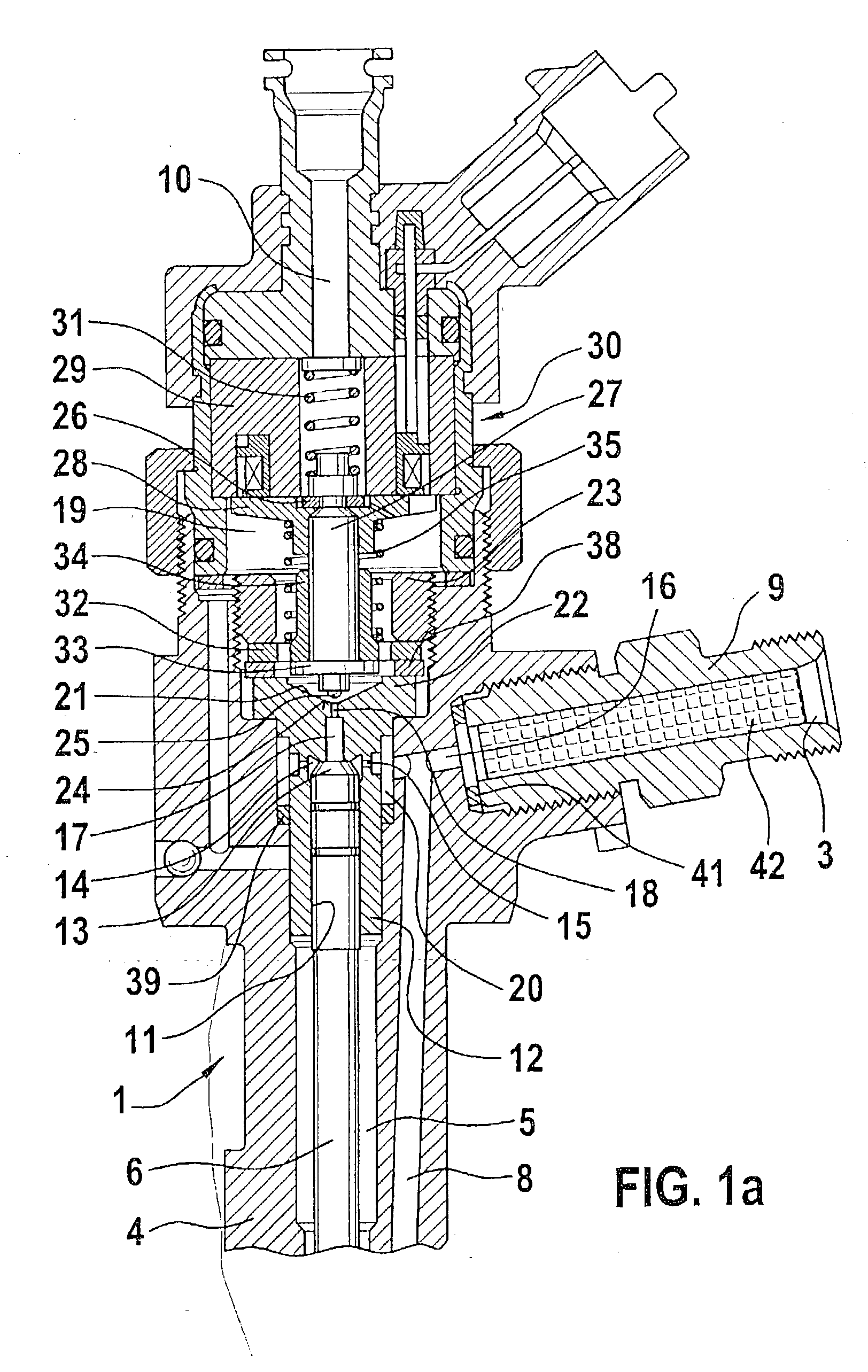
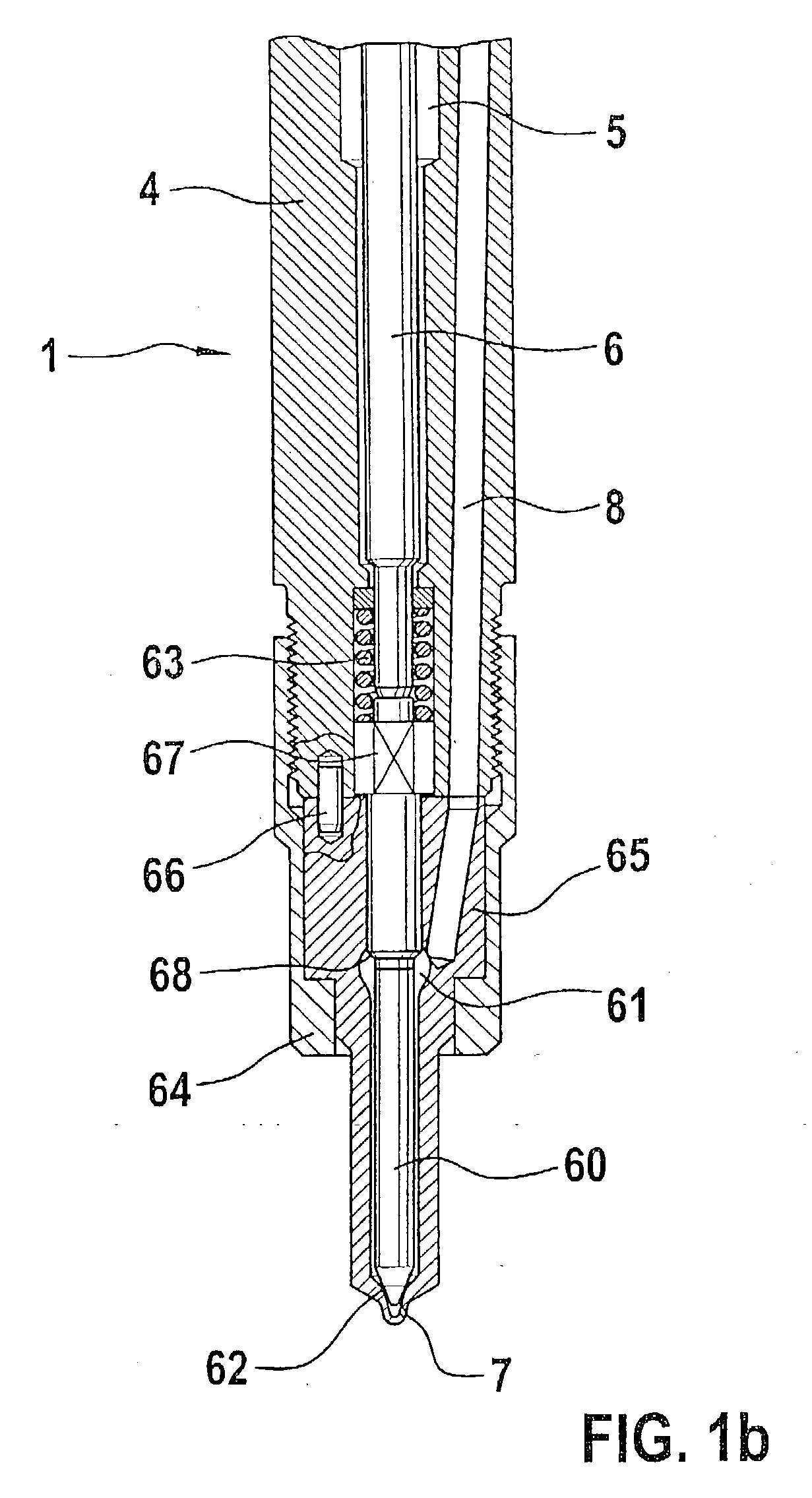
[0016] FIGS. 1a and 1b show a section through an electrically controlled fuel injection valve according to the prior art, for example of the kind disclosed by DE 196 50 865 A1. A fuel injection valve of this kind is intended for use in a fuel injection system equipped with a high-pressure fuel reservoir, which is continuously supplied with high-pressure fuel by a high-pressure feed pump and from which this fuel can be supplied to the internal combustion engine at injection pressure by means of individual electrically controlled injection valves. The fuel injection valve 1 shown in FIGS. 1a and 1b has a valve housing 4 with a longitudinal bore 5, which contains a piston-like part 6 that is embodied for example as a push rod, which at its one end, via a thrust-carrying piece 67, acts on a valve needle 60 disposed in a nozzle body 65, which valve needle 60 closes at least one injection opening 7 in the nozzle body 65 by means of the closing force of a nozzle spring 63 and the closing f...


PUM


Abstract

In a fuel injection valve for internal combustion engines, having a valve housing, having an axially movable valve member for opening and closing an injection opening of the injection valve, and having a part, which acts in the closing direction of the valve member, which is guided with its end remote from the injection opening in a bore of a first valve piece inserted into the valve housing and with this end, encloses a control pressure chamber in the first valve piece, which control pressure chamber can be connected to a high-pressure fuel connection via an inlet conduit, which is provided with at least one inlet throttle, and can be connected to a low-pressure fuel connection via an outlet conduit, which has an outlet throttle and can be closed by a movable control valve member, where the injection process can be controlled by means of the fuel pressure in the control pressure chamber, the proposal is made that at least the section of the inlet conduit provided with the inlet throttle be disposed in a second valve piece inserted into the valve housing, which second valve piece is connected to an opening embodied in the first valve piece in such a way that the section of the inlet conduit of the second valve piece provided with the inlet throttle feeds into the control pressure chamber of the first valve piece.

Description

PRIOR ART[0001] The invention relates to a fuel injection valve with the features of the preamble to claim 1.[0002] A fuel injection valve of this kind, which is also referred to as an injector, has been disclosed for example by DE 196 50 865 A1 and is used in fuel injection systems that are equipped with a high-pressure fuel reservoir. In the known fuel injection valve, fuel pressure prevailing in a control pressure chamber loads a valve needle in the closing direction by means of a valve piston. The control pressure chamber is situated in a valve piece inserted into the valve housing, and this chamber is connected to a high-pressure fuel connection by means of an inlet conduit provided with an inlet throttle and is connected to a low-pressure fuel connection by means of an outlet conduit provided with an outlet throttle. The outlet throttle and inlet throttle are both situated in the same valve piece that is inserted into the valve housing. A valve member of a control valve, which...

Claims


Application Information

Patent Timeline
IPC IPC(8): F02M47/02F02M47/00F02M61/16F02M63/00
CPCF02M47/02F02M2547/003F02M2200/21F02M47/027F02M45/02
Inventor MATTES, PATRICK
Owner ROBERT BOSCH GMBH
Learn More