Method for manufacturing flange for compressor

a manufacturing method and compressor technology, applied in the direction of engines, mechanical equipment, machines/engines, etc., can solve the problems of deteriorating compressor performance, noise generation, deformation of flanges, etc., and achieve the effect of efficient relief grooves

Inactive Publication Date: 2004-04-15
KOREA SINTERED METAL
View PDF8 Cites 2 Cited by
  • Summary
  • Abstract
  • Description
  • Claims
  • Application Information

AI Technical Summary

Benefits of technology

0007] The present invention is designed to overcome problems and drawbacks of the prior art. An object of the present invention is to provide a method for manufacturing a flange, which may simply efficiently form a relief groove on the flange without using any mechanical processing or additional molding.

Problems solved by technology

However, because the rotary axis, which is the core of driving the compressor, is installed to pass through a hollow portion of the flange, the flange may be deformed on the occasion that the rotary axis deforms due to the driving force.
This deformation of the rotary axis may not only deform the flange but also cause melted-bond or abrasion of the flange with the eccentric roller or breakdown of an oil film, which may result in deteriorating performance of the compressor and generating noise.
However, the former mechanical cutting process should be separately performed after molding the flange, so inevitably causing a substantial cost hike.
Moreover, a molding portion corresponding to the relief groove is so weak to be easily broken down or damaged, which causes lower productivity.
Furthermore, since the flange manufactured according to a conventional manner has weak portions around the relief groove, sealing of the flange is not ensured, which is one of basic requirements of the flange.

Method used


Image

  • Method for manufacturing flange for compressor
  • Method for manufacturing flange for compressor
  • Method for manufacturing flange for compressor

Examples


experimental example

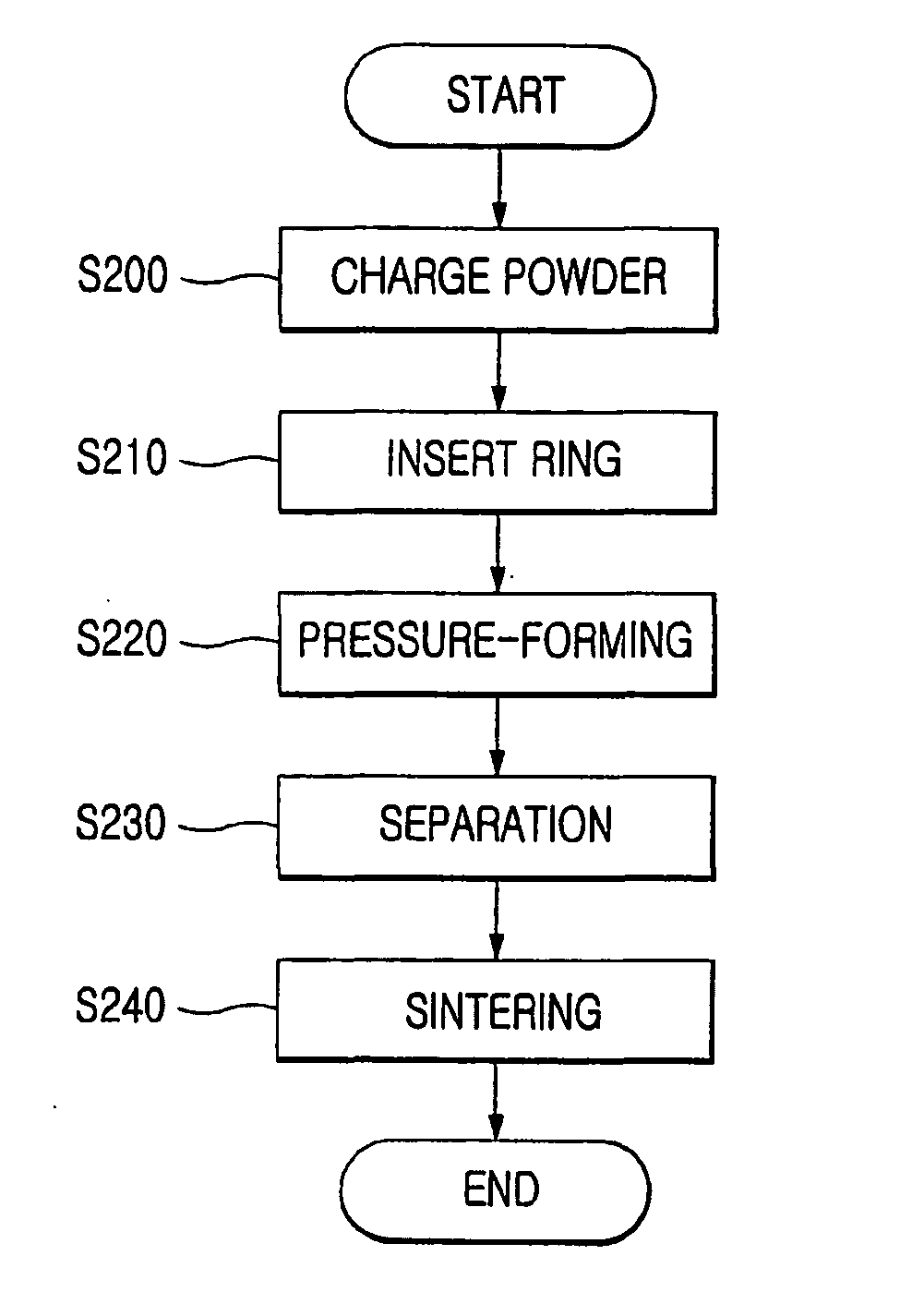
[0030] 1.5 wt % of Cu powder having an average particle size of 45 .mu.m, 0.8 wt % of C powder having an average particle size of 10 .mu.m and the balance of Fe powder having an average particle size of 100 .mu.m are mixed and charged into a mold. Then, the ring-shaped ablative member made of Cu having a purity of 99.9 wt % is positioned around the hollow portion. Then, the mold is compressed together with the ablative member at a pressure of 6 ton / cm.sup.2 to form a flange of the present invention, which is 90 mm in diameter and 50 mm in height. After that, the flange is charged into a sintering furnace and heated at 1,130.+-.30.degree. C. for 30 minutes to melt and remove the ablative member. Through the above procedure, the relief groove having an outer diameter of 27 mm, an inner diameter of 23 mm and 10 mm in depth is completed.

[0031] On the other hand, the prior art forms a relief groove with same size as that of the present invention in the conventional flange through compres...


PUM

PropertyMeasurementUnit
melting pointaaaaaaaaaa
temperatureaaaaaaaaaa

Abstract

To manufacture a flange for a compressor with a relief groove by using powder metallurgy in order to prevent deformation of the compressor in operation, powder material for the flange is charged into a mold; an ablative member having a melting point lower than that of the powder material is positioned at a place where a relief groove is to be formed; the flange is formed by compressing the powder material and the ablative member; and the formed flange is sintered at a temperature between the melting points of the power material and the ablative member so as to melt and remove the ablative member.

Description

[0001] The present invention relates to a method for manufacturing a flange for a compressor, and more particularly to a method for manufacturing a flange for a compressor with a relief groove by using powder metallurgy in order to prevent deformation of the flange in operation.[0002] A compressor is generally used in an air conditioner, a refrigerator and so on for refrigerant compression. A typical example of such a compressor is shown in FIG. 1.[0003] Referring to FIG. 1, a stator 2 and a rotor 3 are installed in a housing 1. In the rotor 3, provided is a rotary axis 4, which is rotatably supported by upper and lower flanges 5 and 6. Also, an eccentric roller 7 is rotatably mounted in a cylinder 8 between the upper and lower flanges 5 and 6 at a lower end of the rotary axis 4.[0004] In the compressor having such configurations, when the rotor 3 turns to rotate the rotary axis 4, the eccentric roller 7 under the rotor 3 also rotates in the cylinder 8 so as to compress refrigerant ...

Claims


Application Information

Patent Timeline
Patent Type & Authority Applications(United States)
IPC IPC(8): B21D53/16B22F5/00B22F5/10
CPCB22F5/10Y10T29/49236F01C21/108B21D53/16
Inventor PARK, JONG-KWAN
Owner KOREA SINTERED METAL
Why Eureka
Try Eureka