Electro-optical device, method of manufacturing electro-optical device, and electronic apparatus

a manufacturing method and electrooptical technology, applied in the direction of optics, semiconductor devices, instruments, etc., can solve the problems of reducing the reflectance of the mirror, affecting the processing efficiency of the inorganic material, and affecting the processing speed of the grinding inorganic material, so as to achieve efficient mirror formation

Active Publication Date: 2016-10-06
SEIKO EPSON CORP
View PDF4 Cites 2 Cited by
  • Summary
  • Abstract
  • Description
  • Claims
  • Application Information

AI Technical Summary

Benefits of technology

[0009]An advantage of some aspects of the invention is to provide an electro-optical device which can efficiently form a mirror without a sacrificial layer remaining on a support post which supports a mirror and without a large dent on a surface of the mirror, a method of manufacturing the electro-optical device, and an electronic apparatus.
[0012]In one or more embodiments of the invention, the second support post (mirror support post) which protrudes toward a side opposite to the substrate from the twist hinge (torsion hinge) is cylindrical, and the first end portion of the substrate side is an open end. For this reason, even though there is a sacrificial layer in the internal side at the time of forming the second support post, the sacrificial layer can be removed. Thus, in the inside of the second support post, the resin configuring the sacrificial layer does not remain. Accordingly, even if the temperature of the electro-optical device increases due to the light which is incident, or heat or the like which is generated in the substrate at the time of operating a drive circuit, gas is not generated from the sacrificial layer. Therefore, a situation in which reflectance of a surface (reflective surface) of the mirror is decreased due to gas which is generated from the sacrificial layer, does not occur. In addition, in a state in which the second end portion is a flat plate in the second support post at a side opposite to the substrate, the mirror separated from the second support post can be coupled to the second support post. For this reason, a dent is not formed on the surface of the mirror. Thus, it is possible to increase utilization efficiency of light, and to prevent contrast from lowering due to scattering at the mirror. In addition, unlike a case in which the concave portion is filled with the inorganic material, it is not necessary to remove a thick inorganic material which fills the concave portion from the mirror, and thus it is possible to efficiently form the mirror support post which does not form a dent on the surface of the mirror. In addition, the second support post which protrudes from the torsion hinge (twist hinge) toward a side opposite to the substrate is a cylindrical, the first end portion on the substrate side becomes the open end, and a second support post is formed as one piece together with the torsion hinge (twist hinge). For this reason, it is possible to prevent strength which is generated in a boundary section between the second support post and the torsion hinge (twist hinge) from decreasing, and the reliability of the electro-optical device increases.
[0015]In one or more embodiments of the invention, it is preferable that an outer peripheral surface of the second support post is a tapered surface facing the mirror side. According to the configuration, it is possible to increase the strength of the second support post.

Problems solved by technology

However, in the same manner as a configuration described in JP-T-2007-510174, in order to fill a concave portion by accumulating an inorganic material, it is necessary to quite thickly accumulate the inorganic material, and in a case of the inorganic material, grinding speed is delayed.
For this reason, there is a problem in which a long processing time is required to grind the inorganic material for removal from a surface of a sacrificial layer or the like.
If the gas is attached to a surface (reflective surface) of the mirror, reflectance of the mirror is decreased, and thus the gas is not desired.
In addition, in order to form a torsion hinge (twist hinge) and a mirror support post, steps of forming a metal layer with two layers and forming an intermediate layer with an insulating property between the metal layers of two layers for patterning are required, and thus a manufacturing step of the electro-optical device is complicated.

Method used


Image

  • Electro-optical device, method of manufacturing electro-optical device, and electronic apparatus
  • Electro-optical device, method of manufacturing electro-optical device, and electronic apparatus
  • Electro-optical device, method of manufacturing electro-optical device, and electronic apparatus

Examples


Embodiment Construction

[0033]Embodiments of the invention will be described with reference to the drawings. In the following description, a projection type display device serving as an electronic apparatus which employs one or more embodiments of the invention will be described. In addition, in the figures referred to by the following description, each layer and each member is illustrated in a recognizable size in the figures, and scales are different from each other for each layer and each member. In addition, the number of mirrors or the like is reductively illustrated in the drawings.

Projection Type Display Device Serving as Electronic Apparatus

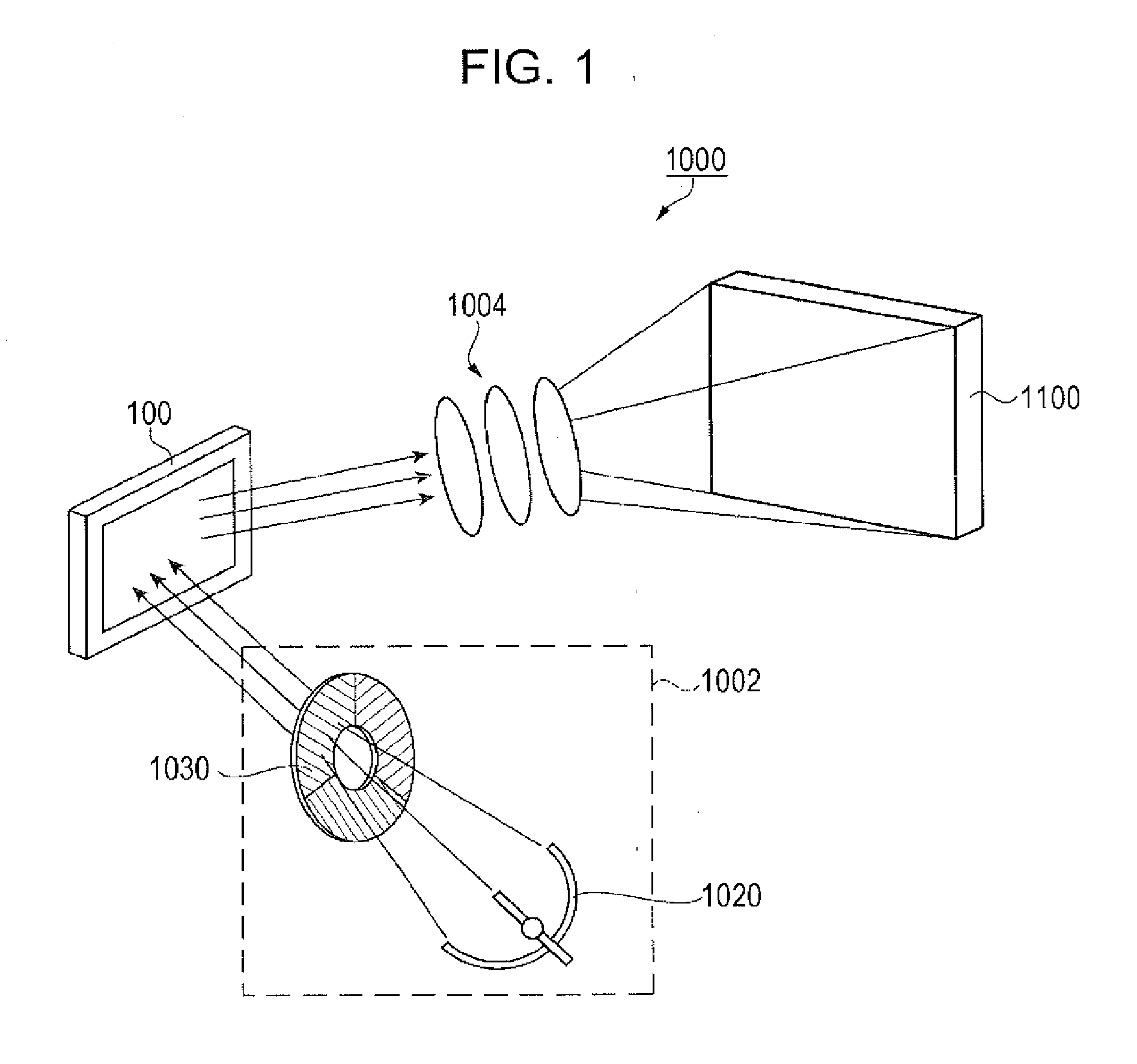
[0034]FIG. 1 is a schematic view illustrating an optical system of a projection type display device serving as an electronic apparatus which employs an embodiment of the invention. The projection type display device 1000 illustrated in FIG. 1 includes a light source unit 1002, an electro-optical device 100 which modulates light emitted from the light source unit...


PUM


Abstract

In an electro-optical device, a torsion hinge and a mirror support post are formed as one piece together with a conductive member, and in the mirror support post, a first end portion on a substrate side is an open end which is opened toward the substrate. In the mirror support post, a second end portion on a mirror side is a flat plate which closes an opening of the mirror support post, and the mirror is in contact with a surface of the flat plate at a side opposite to the substrate. The first sacrificial layer which is used for manufacturing the electro-optical device is formed by exposure, development, and etching in a state in which a hard mask is formed, with respect to the photosensitive resin layer.

Description

CROSS-REFERENCE TO RELATED APPLICATIONS[0001]This is a Division of application Ser. No. 15 / 057,402 filed Mar. 1, 2016, which claims priority to Japanese Patent Application JP 2015-074869, filed Apr. 1, 2015. The disclosures of the prior applications are hereby incorporated by reference herein in their entirety.BACKGROUND[0002]1. Technical Field[0003]Various embodiments of the present invention relate to an electro-optical device including a mirror, a method of manufacturing the electro-optical device, and an electronic apparatus.[0004]2. Related Art[0005]For example, a projection display device, which modulates light emitted from a light source using a plurality of mirrors (micro mirrors) of an electro-optical device called a digital mirror device (DMD), enlarges the modulated light to project using a projection optical system, thereby displaying an image onto a screen, is known as an electronic apparatus. In the electro-optical device which is used for the electronic apparatus, the...

Claims


Application Information

Patent Timeline
Patent Type & Authority Applications(United States)
IPC IPC(8): G02B26/08
CPCG02B26/0841H01L33/48H01L33/62H01L2933/0033H01L2933/0066
Inventor ITO, SATOSHI
Owner SEIKO EPSON CORP
Why Eureka
Try Eureka