Array antenna

Active Publication Date: 2005-11-24
FURUNO ELECTRIC CO LTD
View PDF7 Cites 2 Cited by
  • Summary
  • Abstract
  • Description
  • Claims
  • Application Information

AI Technical Summary

Benefits of technology

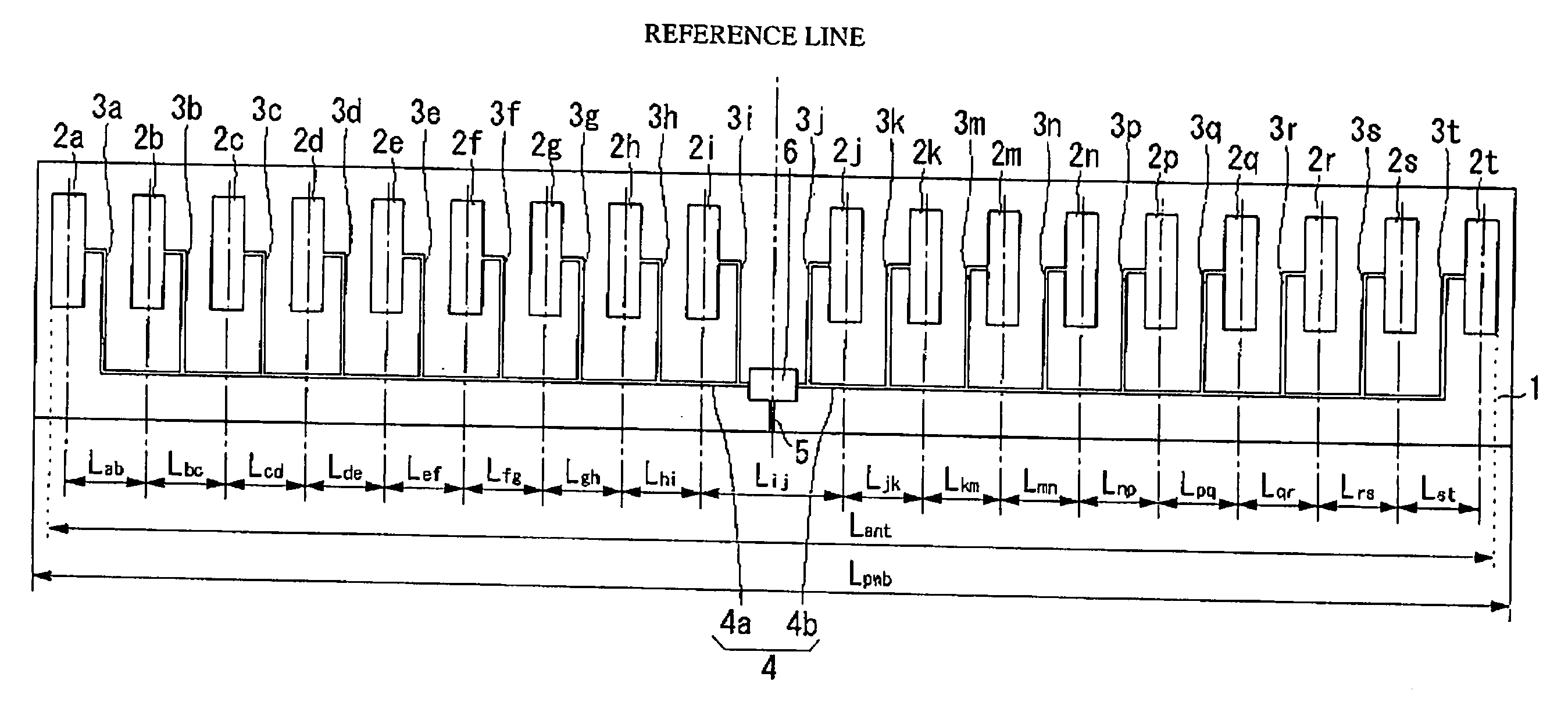
[0010] In light of the foregoing, it is an object of the invention to provide an array antenna having desired

Problems solved by technology

As a result, the substantial antenna length Lant is shorter than the overall length Lpwb of the sub

Method used


Image

  • Array antenna
  • Array antenna
  • Array antenna

Examples


Example

[0026] An array antenna according to a first embodiment of the invention is now described with reference to FIGS. 1 to 3 and Tables 1 and 2.

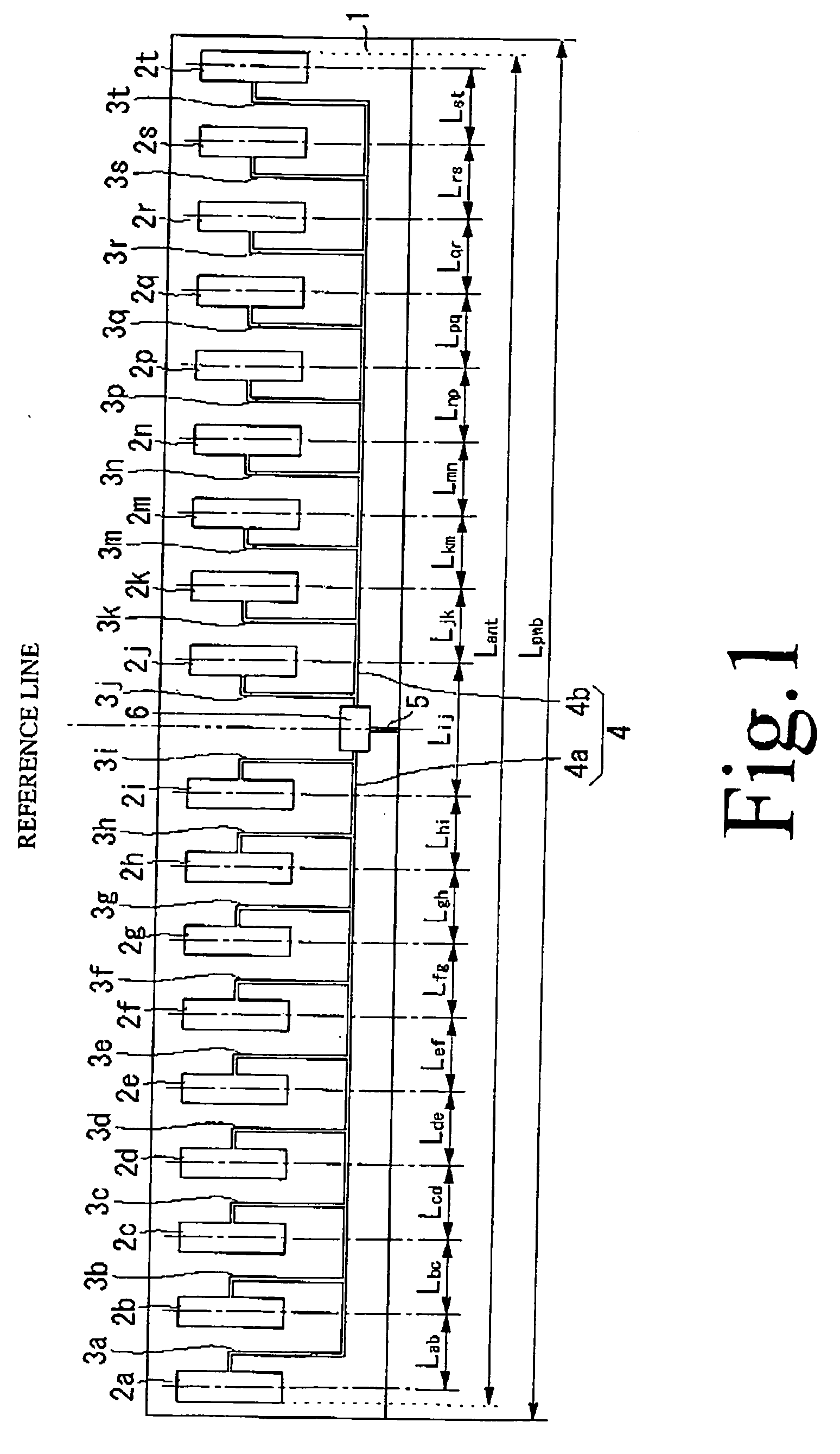
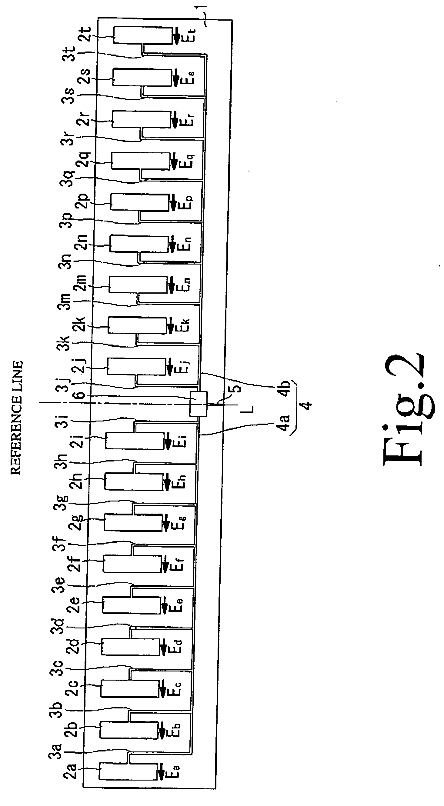
[0027]FIG. 1 is a plan view generally showing the configuration of the array antenna according to the first embodiment of the invention. Referring to FIG. 1, the array antenna includes a substrate 1 having a rectangular shape in plan view and a plurality of antenna elements 2a-2t formed on a surface of the substrate 1, the antenna elements 2a-2t being arranged in a predetermined array pattern. The array antenna further includes a plurality of secondary feeder lines 3a-3t, a primary feeder line 4, an outgoing line 5 and a phase-inverting distributor 6 which are also formed on the surface of the substrate 1. The substrate 1 is made of a dielectric material while the antenna elements 2a-2t, the secondary feeder lines 3a-3t, the primary feeder line 4 and the outgoing line 5 are made of a patterned conductor layer (including conductor lines and elec...

Example

[0046] An array antenna according to a second embodiment of the invention is now described with reference to FIG. 4 and Tables 3 and 4.

[0047] The array antenna of the second embodiment has basically the same configuration as the array antenna of the first embodiment (refer to FIG. 1) except that the intervals between the successive antenna elements 2a-2t and the amounts of attenuation in the individual antenna elements 2a-2t in the array antenna of the second embodiment are varied from those of the first embodiment.

[0048] Table 1 shows the intervals Lab-Lst between the successive antenna elements 2a-2t, and Table 2 shows the amounts of attenuation from the phase-inverting distributor 6 to the individual antenna elements 2a-2t including attenuation in the primary feeder line 4 and the respective secondary feeder lines 3a-3t. TABLE 3SymbolElement-to-element interval (mm)Lab25.65Lbc23.40Lcd21.90Lde21.65Lef21.75Lfg21.65Lgh22.15Lhi23.50Lij25.65Ljk23.50Lkm22.15Lmn21.65Lnp21.75Lpq21.65L...


PUM


Abstract

Antenna elements are arranged in line on a surface of a substrate at specific intervals along a longitudinal direction of the substrate. A phase-inverting distributor is formed on the surface of the substrate in an area located between two antenna elements which are closest to and located on both sides of a vertical centerline, or a reference line, of the substrate. A primary feeder line formed along the longitudinal direction of the substrate extends from the phase-inverting distributor on both left and right sides thereof. The individual antenna elements are connected to the primary feeder line by secondary feeder lines having predetermined impedances. The secondary feeder lines are connected to the respective antenna elements on sides thereof which are perpendicular to the longitudinal direction of the substrate and face the reference line on which the phase-inverting distributor is located.

Description

BACKGROUND OF THE INVENTION [0001] 1. Field of the Invention [0002] The present invention relates to an array antenna on which a plurality of antenna elements for radiating radio waves are arranged generally in line, forming a linear array. [0003] 2. Description of the Related Art [0004] There exist various kinds of conventionally known array antennas employing a configuration in which a plurality of antenna elements are formed on a substrate and the individual antenna elements are connected to secondary feeder lines which are arranged parallel to one another. [0005]FIG. 6 is a plan view generally showing the configuration of a conventional array antenna on which a plurality of antenna elements are arranged generally in line. This kind of conventional array antenna is shown in Japanese Patent Application Publication No. 1999-312909, in which antenna elements are arranged side by side as shown in FIG. 6. [0006] Referring to FIG. 6, the array antenna includes a substrate 1 having a re...

Claims


Application Information

Patent Timeline
IPC IPC(8): H01Q21/08H01Q21/00H01Q21/06
CPCH01Q21/0006H01Q21/065H01Q21/0075H01Q21/06
Inventor KOREYASU, MISATAKASHIMA, TETSUYAHIRAOKA, KATSUFUMIHINO, AKIHIRO
Owner FURUNO ELECTRIC CO LTD
Why Eureka
Try Eureka