Optical connector plug, optical connector adapter and optical connector

a technology of optical connectors and adapters, applied in the direction of optics, printed circuits, instruments, etc., can solve the problems of restriction of use, complex welding steps, and inability to attach and detach the optical connection of the optical fibers

Inactive Publication Date: 2004-04-15
SEIKOH GIKEN
View PDF3 Cites 77 Cited by
  • Summary
  • Abstract
  • Description
  • Claims
  • Application Information

AI Technical Summary

Problems solved by technology

According to the optical connection of theoptical fibers by welding, there pose a problem that attachment and detachment of the optical connection of the optical fibers cannot be carried out, and a problem that welding steps are complicated which gives rise to a problem that there is a restriction in use thereof.
Therefore, a number of parts is large and downsizing thereof is difficult.
Therefore, a wide mounting are is needed for mounting a comparatively small-sized MU type optical connector at a mounting board and there poses a problem that downsizing of the mounting board per se cannot be achieved.
Further, when the optical connector of the related art is mounted to the mounting board, the optical adapter is directly fixed to the mounting board and therefore, a space for attaching and detaching the optical connector plug holding the optical fiber is needed on the mounting board and there poses a problem that not only the mounting board is large-sized but also operational efficiency is poor.
Further, there poses a problem that numbers of parts are large and integration is difficult in respectives of the optical connector flag and the optical connector adapter of the optical connector of the related art.
However, according to the above-described optical connector using the leaf spring, there poses a problem that owing to durability performance of the leaf spring, when attachment and detachment are repeated, durability of the leaf spring is deteriorated, a deterioration in opposing connection of optical fibers, that is, a deterioration in insertion loss is brought about and therefore, a number of times of attachment and detachment is restricted.
Further, according to the above-described optical connector using the leaf spring, there is not means for restricting movement of the ferrule holding the front end of the optical fiber in a rotating direction centering on an axis thereof, an eccentric direction of the core of the optical fiber cannot be prescribed and the inserting loss is increased by bringing about an eccentric shift of the core.
Further, according to the above-described optical connector using the leaf spring, there poses a problem that the ferrule is liable to disengage from the leaf spring by vibration and impact and the reliability is poor.
Further, according to the above-described optical connector using the leaf spring, the front end portion of the cylindrical body for ferrule is directly inserted into a sleeve for optical connection and therefore, there poses a problem that a defect is liable to be brought about at the polished front end face of the cylindrical member for ferrule when an inserting angle is large or by repeating attachment and detachment, the inserting loss in optical connection is liable to increase and the reliability is poor.

Method used


Image

  • Optical connector plug, optical connector adapter and optical connector
  • Optical connector plug, optical connector adapter and optical connector
  • Optical connector plug, optical connector adapter and optical connector

Examples


embodiment 1

1 embodiment 1 related art total length (mm) 12.8 35 width (mm) 4.5 6.6 height (mm) 3.6 4.35 number of parts 4 7

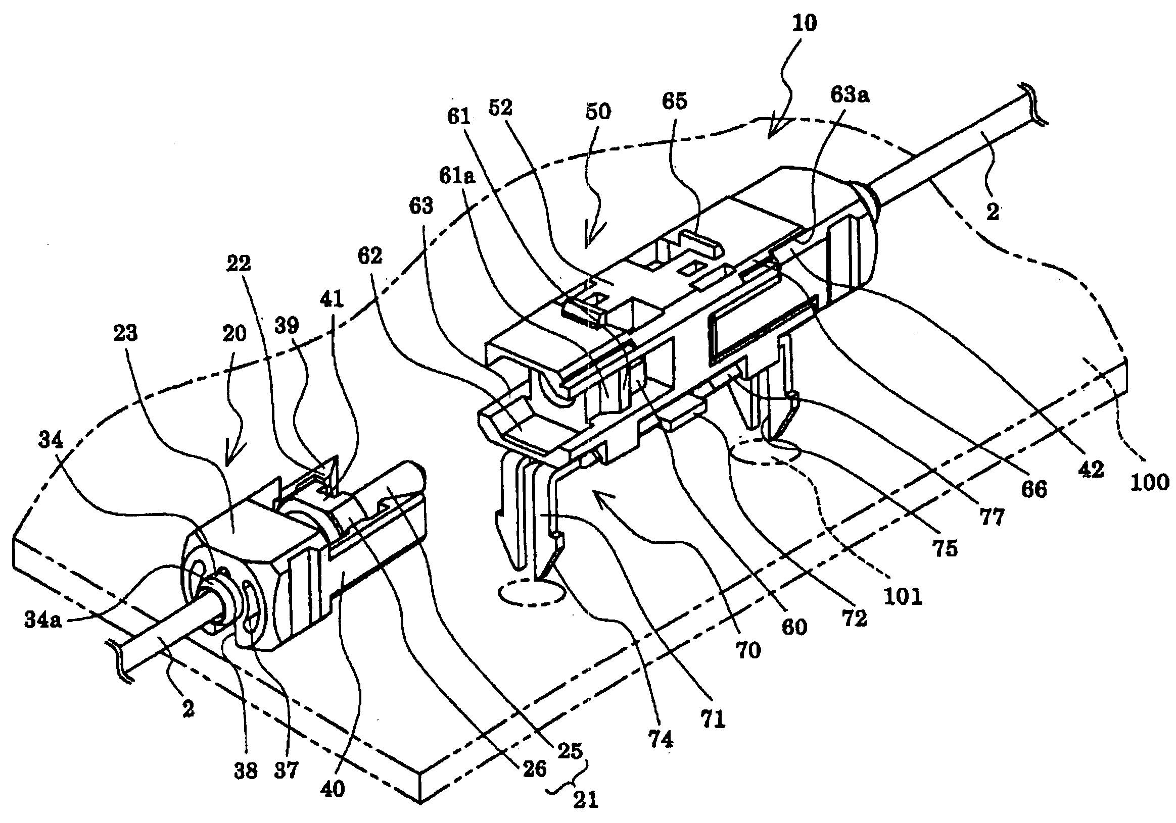
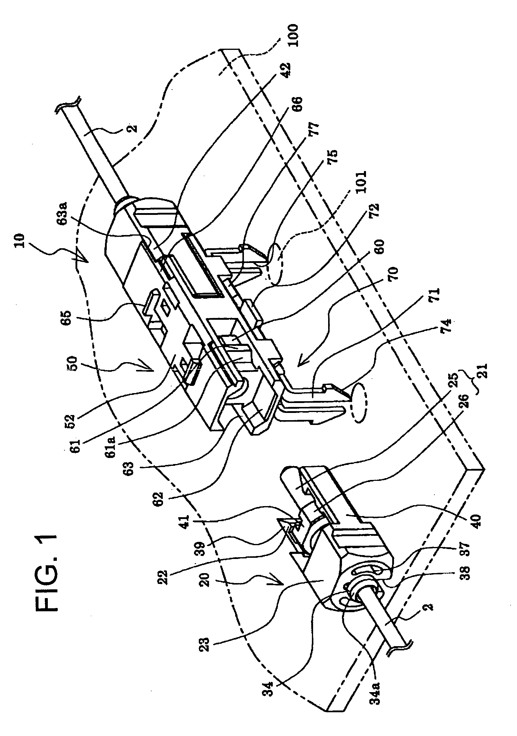
[0100] As shown by Table 1, a number of parts of the optical connector plug 20 of Embodiment 1 is smaller than that of the MU type optical connector plug of the related art and all of the total length, the width and the height can be downsized. Thereby, downsizing of the optical connector 10 using the optical connector plug 20 can be achieved and when the optical connector 10 is mounted to a mounting board, high density formation can be achieved.

[0101] Further, the optical connector 10 using the optical connector plug 20 optically connects the optical fiber core lines 2 provided with coatings at outer peripheries of the optical fibers 1 above a mounting board 100 and therefore, it is not necessary to use an optical fiber cable provided with a tension member and a coating at the-outer periphery of the optical fiber core line 2 and downsizing can be carried out also thereby....

embodiment 2

[0164] FIG. 10 is a perspective view showing a step of mounting to laminate optical connectors according to Embodiment 2 and FIG. 11 is a perspective showing a state of mounting to laminate optical connecters according to Embodiment 2. Further, members similar to those of Embodiment 1, mentioned above, are attached with the same notations and duplicated explanation thereof will be omitted.

[0165] As shown by FIG. 10 and FIG. 11, an optical connector 10A is provided with the optical connector plug 20, an optical connector adapter 50A and a mounting member 70A.

[0166] The mounting member 70A comprises the bent portion 71 and a base seat portion 72A and adapter engaging portions 77A are provided at edge portions on both sides in a width direction of the base seat portion 72A.

[0167] The adapter engaging portions 77A are formed to bend to project to a side opposed to the bent portion 71 and formed such that front end portions thereof are bent to both sides in the width direction to constit...

embodiment 3

[0174] FIG. 12 is a perspective view showing a step of integrating an optical connector adapter according to Embodiment 3 and FIGS. 13A and 13B are a plane view of the optical connector adapter and a sectional view taken along a line F-F' thereof. Further, members similar to those of Embodiments land 2, mentioned above, are attached with the same notations and a duplicated explanation thereof will be omitted.

[0175] As shown by FIG. 12 and FIGS. 13A and 13B, an optical connector adapter 50B of the embodiment is provided with the sleeve for optical connection 51 inserted with a front end portion of a cylindrical member for ferrule and an adapter housing 52B including the sleeve for optical connection 51 and an adapter housing 52B and is constituted by a housing main body 110 provided with a sleeve inserting hole 58B inserted with the sleeve for optical connection 51 and opened at one face thereof and a lid member 120 fitted to the sleeve inserting hole 58B of the housing main body 110...


PUM


Abstract

To provide an optical connector promoting reliability by reducing insertion loss of an optical fiber and downsized, there is provided an optical connector plug having a ferrule including a cylindrical member for the ferrule for holding an optical fiber and a flange member provided at a rear end portion of the cylindrical member for the ferrule, an urge spring provided on a side of a rear end portion of the flange member of the ferrule, and a plug housing for holding the ferrule and the urge spring directly at inside thereof and directly engaged with an optical connector adapter inserted with a front end portion of the ferrule to carry out optical connection, in which the plug housing is formed with a slit capable of inserting the optical fiber in a radius direction thereof at a portion of an outer periphery thereof over an axial direction.

Description

[0001] 1. Field of the Invention[0002] The present invention relates to an optical connector plug and an optical connector adapter as well as an optical connector for holding a front end of an optical fiber and optically connecting the optical fibers.[0003] 2. Description of the Related Art[0004] In a related art, optical connection of optical fibers used in optical communication is carried out by a method of using an optical connector having an optical connector plug holding a front end of the optical fiber and an optical connector adapter for carrying out optical connection of the optical fibers by fixing the optical connector plugs, or a method of welding front end faces of the optical fibers.[0005] According to the optical connection of theoptical fibers by welding, there pose a problem that attachment and detachment of the optical connection of the optical fibers cannot be carried out, and a problem that welding steps are complicated which gives rise to a problem that there is ...

Claims


Application Information

Patent Timeline
Patent Type & Authority Applications(United States)
IPC IPC(8): G02B6/38
CPCG02B6/3807G02B6/3821G02B6/3825G02B6/3898G02B6/3879G02B6/3893G02B6/3897G02B6/3877
Inventor NAKAJIMA, MASAHIROMINAMI, KOUJITAIRA, JUNJI
Owner SEIKOH GIKEN
Why Eureka
Try Eureka