Adjustable gate hinge having stamped metal pivot components

a technology pivot components, which is applied in the field of adjustable gate hinges, can solve the problems of increasing production costs, significantly increasing costs, and significantly slowing down machining operations, and reducing production efficiency

Inactive Publication Date: 2004-05-20
SOSA SAUL S
View PDF10 Cites 52 Cited by
  • Summary
  • Abstract
  • Description
  • Claims
  • Application Information

AI Technical Summary

Problems solved by technology

As a general rule, machining operations are significantly more expensive and significantly slower than progressive, high-speed sheet metal stamping operations.
The requirement for machined and bead-welded components in the hinge assembly 100 raises the production cost thereof.

Method used


Image

  • Adjustable gate hinge having stamped metal pivot components
  • Adjustable gate hinge having stamped metal pivot components
  • Adjustable gate hinge having stamped metal pivot components

Examples


Embodiment Construction

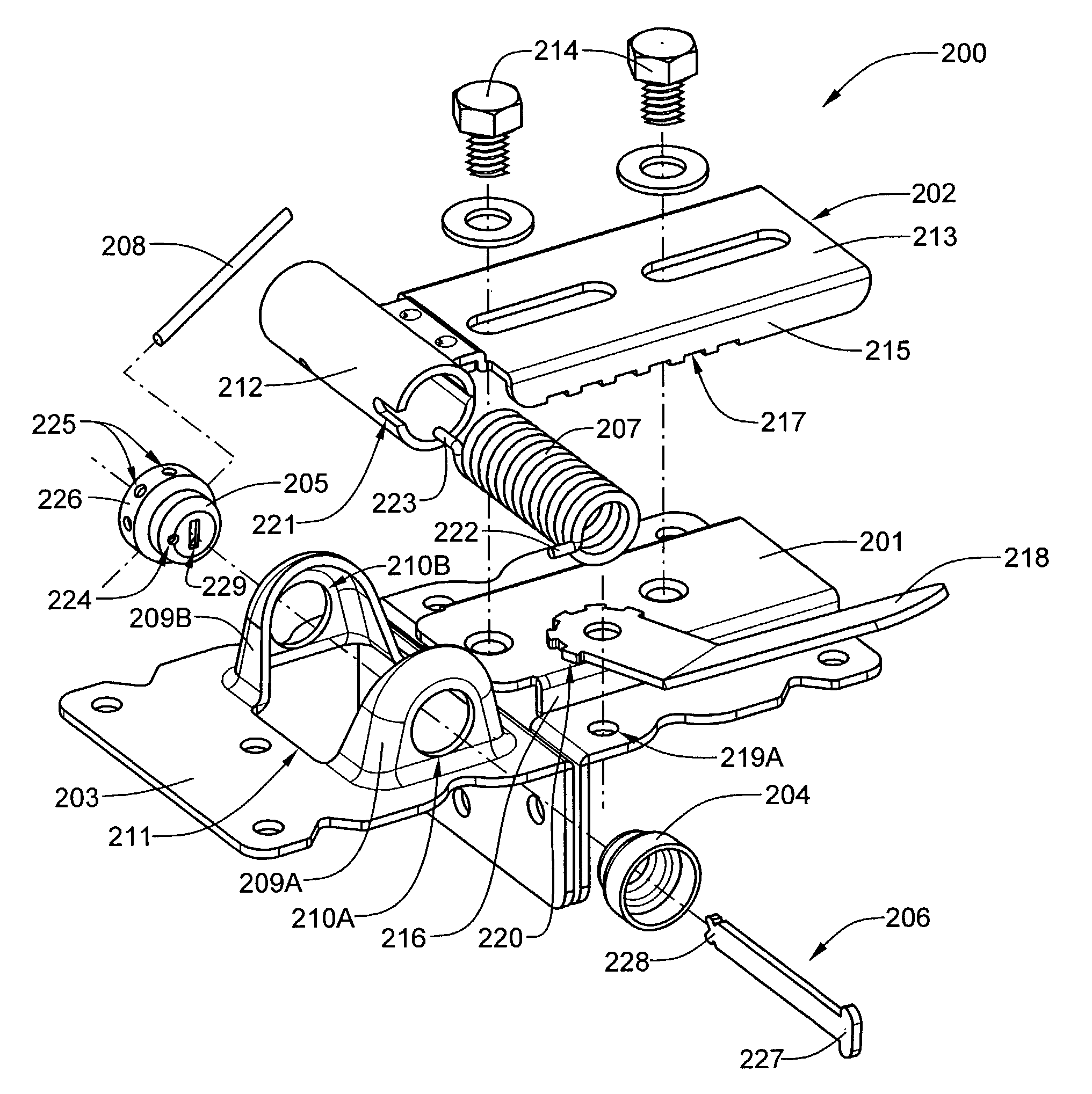
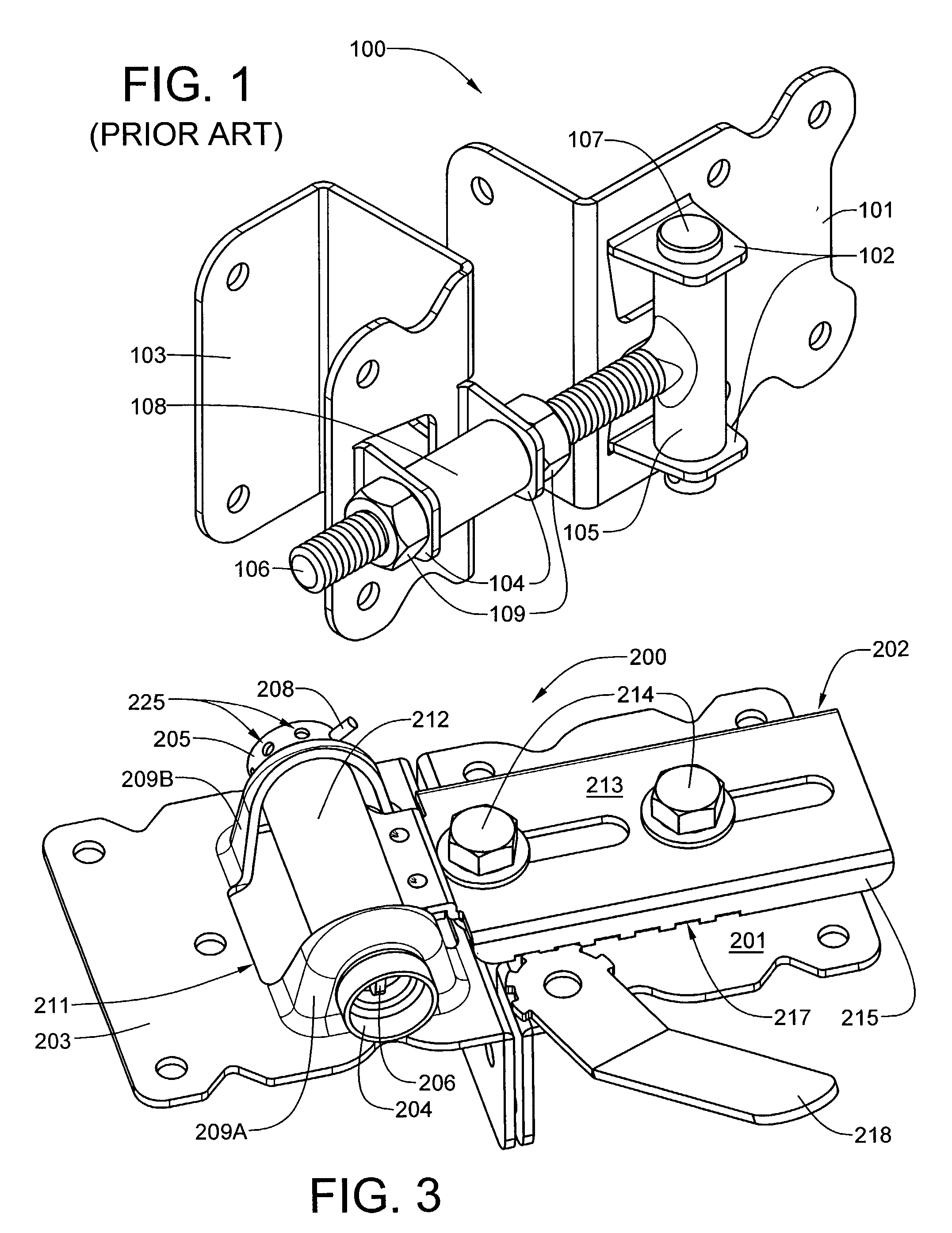
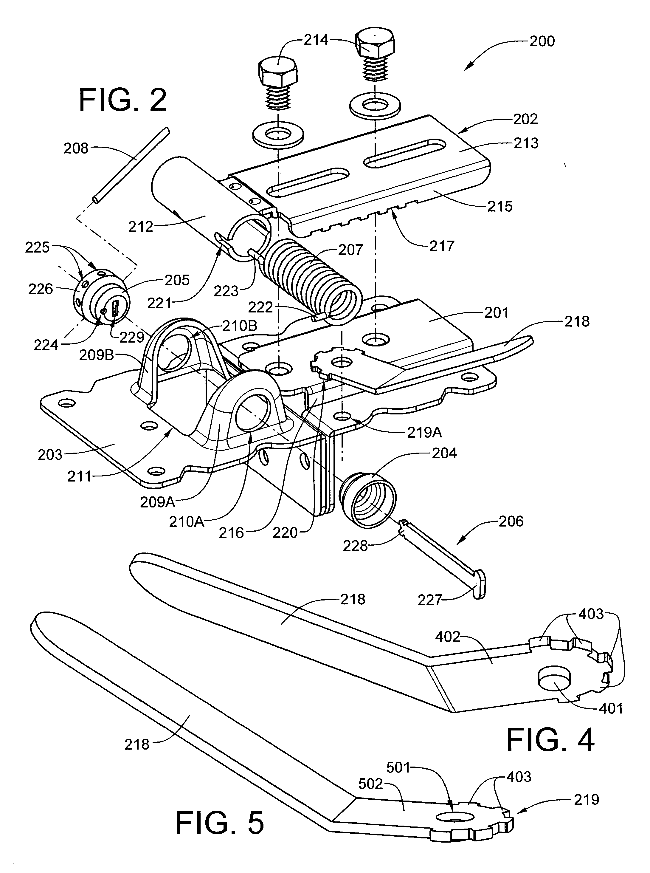
[0034] The new adjustable gate hinge assembly is both stronger and less expensive to manufacture than conventional gate hinges fabricated from sheet metal stampings and machined parts. Rather than using a pair of solid, machined pivot caps which are riveted together with a machined pin, the present invention uses a pair of stamped pivot caps held together with a peened or swedged rivet. This feature, alone, results in substantial cost savings in the fabrication of the new gate hinge assembly. In addition, by using a metal forming process which not only cuts and bends, but also draws the sheet metal, cantilevered pivot ears are eliminated by the new design. Moreover, the new gate hinge assembly eliminates the threaded adjustment rod in favor of a slidable shank that is bolted to a base plate. The new adjustable gate hinge will now be described with reference to the accompanying drawing FIGS. 2 through 21C.

[0035] Referring now to the exploded view of FIG. 2, a preferred embodiment of ...


PUM


Abstract

An adjustable gate hinge assembly fabricated from stamped components is both stronger and less expensive to manufacture than currently manufactured designs. The hinge assembly includes a base plate mountable to a gate or door, an inner hinge component slidably adjustable and securable to the base plate with threaded fasteners, an outer hinge component mountable to a fence or wall, first and second pivot plugs which locate the inner hinge component within the outer hinge component, and a rivet which passes through the slot of each pivot plug, thereby retaining them seated within the outer hinge component. The inner hinge component has a tubular member which pivots between a pair of opposed drawn ears on the outer hinge component. Each of the ears has an aperture that is axially aligned with the aperture of the other ear. For a preferred embodiment of the invention, the hinge assembly incorporates a coil spring within the tubular member, which can be loaded to bias the hinge as self-closing or self-opening.

Description

[0001] 1. Field of the Invention[0002] This invention broadly relates to hinges for use with gates or other swinging structures. More particularly, the invention relates to adjustable gate hinges fabricated from stamped metal components.[0003] 2. Description of Related Art[0004] Gates, and in particular gates used with fencing to provide access to a field or enclosure are well-known, it being typically desired to have the gate level to preserve the swinging function of the gate (e.g., avoid dragging the gate on the ground) and to present a pleasing appearance. Upper and lower hinges are used to support the gate while it swings between a closed position in general alignment with the fence and an open position to permit access through the gate. Most modern hinges incorporate a high degree of adjustability so that the gate, to which the hinges are attached, may be positioned in a level attitude.[0005] The gate hinges disclosed in U.S. Design Patents No. D396,626 to D. Francom and No. D...

Claims


Application Information

Patent Timeline
IPC IPC(8): E05D7/04E05D9/00E05F1/12
CPCE05D7/04E05D7/0423E05D9/00E05F1/1215Y10T16/538633E05Y2800/692E05Y2900/40E05Y2900/132Y10T16/5381E05Y2600/626
Inventor SOSA, SAUL S.SHEETZ, JARED W.
Owner SOSA SAUL S
Why Eureka
Try Eureka