Self-adjusting re-sealable spring center seal closure

a seal closure and self-adjusting technology, applied in the field of plastic containers and lids, can solve the problems of injection molded plastic containers not being recycled, not providing a container that is well suited, and difficulty in removing the lid from frozen containers, etc., and achieve the effect of convenient removal

Inactive Publication Date: 2004-05-20
GRAHAM PACKAGING CO LP
View PDF10 Cites 44 Cited by
  • Summary
  • Abstract
  • Description
  • Claims
  • Application Information

AI Technical Summary

Benefits of technology

[0015] Another object of the present invention is to provide an improved container and lid combination that withstands the rigors of the filling and freezing processes, yet remains leak-resistant throughout normal handling of the container.
[0018] The present invention provides a lightweight re-usable liquid seal closure to reduce plastic weight in current packages. The present invention provides the consumer with an easy on and off removable lid that is reusable while still maintaining a consistent secondary seal.
[0020] The spring mechanism allows for a reduction in the weight of the lid by removing the need for further reinforcement to withstand abuse. This weight reduction is achieved by reducing the need for a rigid central planar region. Instead, the central planar region can be thinner, using less material, and less rigid. A weight reduction of up to about 32.4% can be achieved while still maintaining abuse standards. The spring design also adapts to the inconsistency of manufacturing of the container flange. For example, a container flange in a typical frozen juice package may vary by up to 0.03 inch. A variation of up to about 0.10 inch in flange length can be accommodated by the spring design lid of the present invention.
[0022] The present invention overcomes the limitations of prior art container and lid combinations by means of a novel container lid configuration described herein which cooperates with standard containers that are currently commercially available, to provide a commercially desirable container that can withstand the rigors of freezing, yet remain leak-resistant before and after opening, use and resealing by the consumer. The lid includes tamper-evidence band, and is easy to remove, even when the container and contents are still frozen. In addition, the container and lid allows the consumer to reapply the lid onto the container after partial withdrawal of the contained product, or for other purposes.

Problems solved by technology

This construction does not provide a container that is well suited for partial consumption of its contents and re-closure.
Furthermore, removal of the lid from the frozen container is not always without difficulty.
However, injection molded plastic containers are not currently being recycled and this is a major disadvantage of such containers.
However, with blow molding techniques, dimensional tolerances are more difficult to control.
A problem associated with freezable blow-molded containers is the need to accommodate slight changes in configuration due to changes in volume as the liquid freezes after the container has been sealed with a lid.
Home-made solutions are generally not sturdy enough to withstand being dropped.
Another shortcoming of current container closures is that they cannot adjust to variations in the length of a flange at the open end of the container, particularly when the container is manufactured by a blow molding process.
These variations make it more difficult for the closure to achieve and maintain a consistent seal.
However, this added weight is large enough to slow down the injection cycle time.
A slow injection cycle means that fewer closure units can be manufactured at a time, reducing the ability of the manufacturer to supply units for filling.
Reducing the weight of the closure has the potential, however, to degrade performance under abuse, such as when the container is dropped.
Similarly, once the tamper-evident seal is removed, current containers suffer a large reduction in their ability to withstand abuse.

Method used


Image

  • Self-adjusting re-sealable spring center seal closure
  • Self-adjusting re-sealable spring center seal closure
  • Self-adjusting re-sealable spring center seal closure

Examples


Embodiment Construction

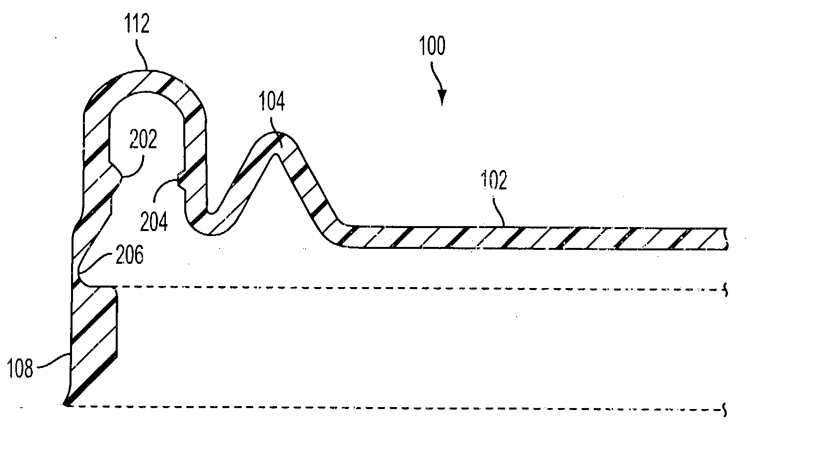
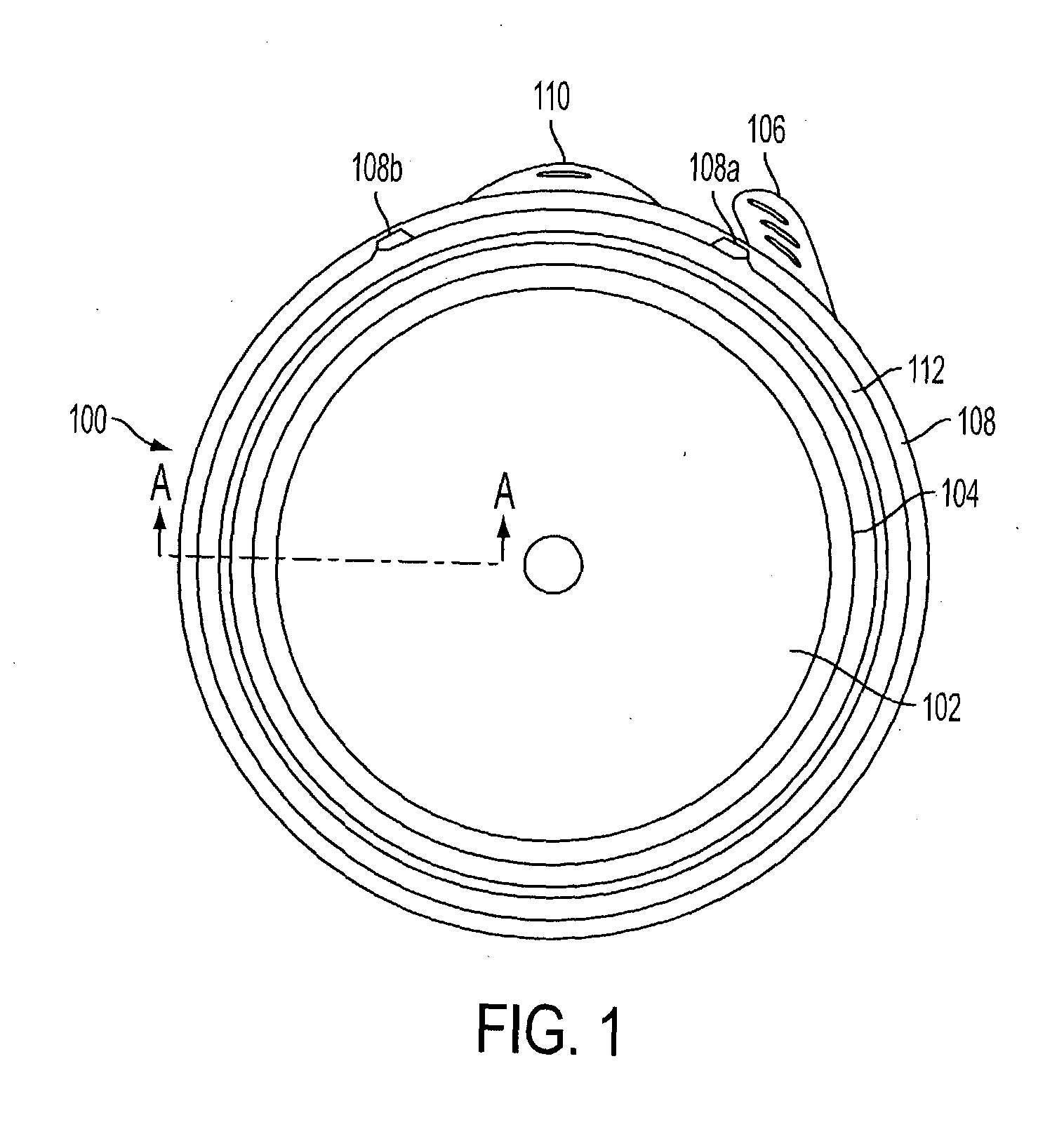
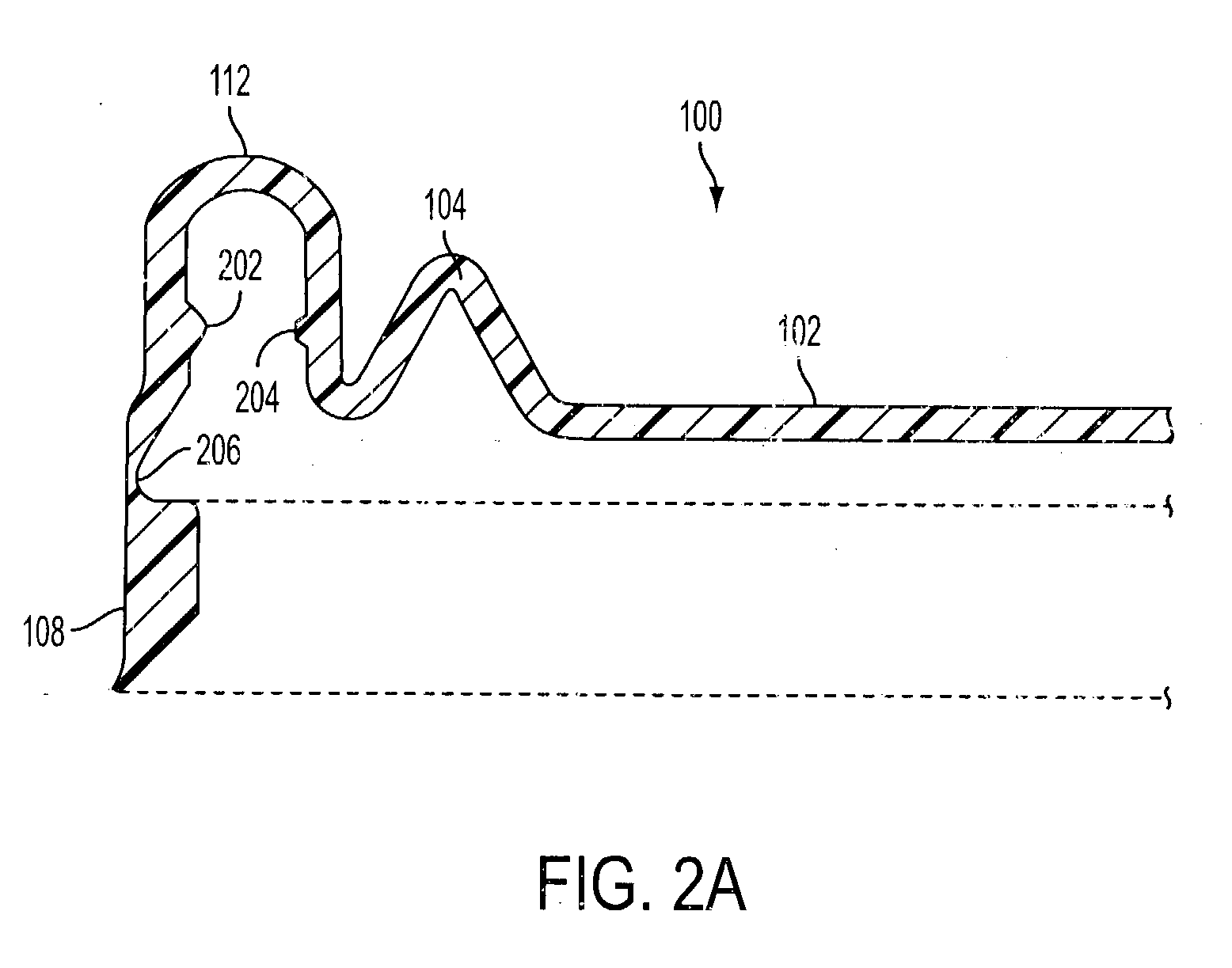
[0030] As can be seen from FIGS. 1 and 2A, a lid 100 according to the present invention is substantially circular and has a substantially planar center region 102. A spring 104 surrounds the center region 102. The spring 104 in the illustrated embodiment is an annular formation that bends in one direction out of the plane defined by the center region 102 and then bends back. The lid 100 also has a pull-tab 106 to remove a tamper-evident seal 108 clockwise from a break point 108a to a breakpoint 108b. In the illustrated embodiment, the seal 108 is a band that extends annularly around the lid 100 and a container that the lid covers. A push-up tab 110 remains on the lid 100 after the tamper-evident seal 108 is removed, allowing the user to push the lid up and remove it from the container. The lid 100 also includes an arcuate flange receiving portion 112 near the perimeter of the lid 100 to receive the flange of a container.

[0031] As can be seen from FIG. 2A, the flange receiving portio...


PUM

PropertyMeasurementUnit
lengthaaaaaaaaaa
circumferenceaaaaaaaaaa
sealing pressureaaaaaaaaaa

Abstract

A leak-resistant plastic container and closure are disclosed, where the container has an open end, an inner periphery, an outer periphery, and a container flange extending around the inner periphery at the open end. The closure has a generally planar and circular inner lid, a spring extending around an outer circumference of the inner lid, an arcuate flange receptacle extending around an outer circumference of the closure at a circumference outside the spring, where the flange receptacle has an inner surface and an outer surface, a secondary sealing bead, positioned on the inner surface of the flange receptacle, and a primary sealing bead, positioned on an outer surface of the flange receptacle and opposite the secondary sealing bead, where the spring exerts a sealing pressure against the container flange when the closure is placed on the open end of the container.

Description

[0001] 1. Field of the Invention[0002] The present invention relates to a plastic container and lid and, more particularly, to a lightweight easy on and off lid with a reusable liquid seal closure.[0003] 2. Related Art[0004] Many food and beverage products sold to the consuming public are provided in wide mouth jar-like containers. Consumers have indicated that they prefer containers which initially have a tamper-evident seal, and which can be resealed after opening for partial consumption of the contents. It is imperative that any such container have a seal which is leak-resistant from the time the lid is applied until end use by the consumer.[0005] While seal integrity is important, the lid should allow for easy removal by the consumer. Therefore, a commercially-desirable container should have a reliable seal and a lid that is easily removed, even if the container and its contents are frozen.[0006] Conventional containers for frozen juice concentrate have been constructed with a c...

Claims


Application Information

Patent Timeline
Patent Type & Authority Applications(United States)
IPC IPC(8): B65D43/02
CPCB65D2543/00796B65D2543/00842B65D43/0249B65D2101/0038B65D2543/00092B65D2543/00296B65D2543/0074B65D2543/00537B65D2543/00555B65D2543/0062B65D2543/00629B65D2543/00685B65D2543/00731B65D2543/00509B65D2401/25
Inventor CRIDER, MATTHEWHERRING, WALT
Owner GRAHAM PACKAGING CO LP
Why Eureka
Try Eureka