

Display device and electronic apparatus
a technology of electronic equipment and display device, which is applied in the direction of electronic switching, digital storage, instruments, etc., can solve the problem that the display device has not yet had such a function
- Summary
- Abstract
- Description
- Claims
- Application Information
AI Technical Summary
Problems solved by technology
Method used
Image

Examples
embodiment mode 1
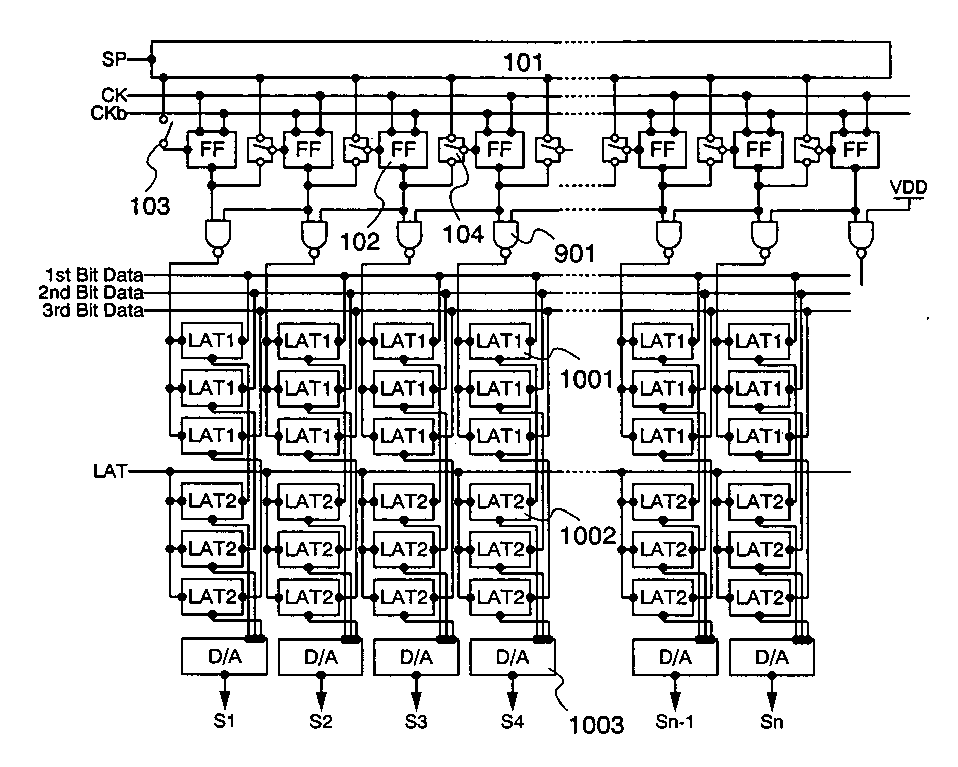
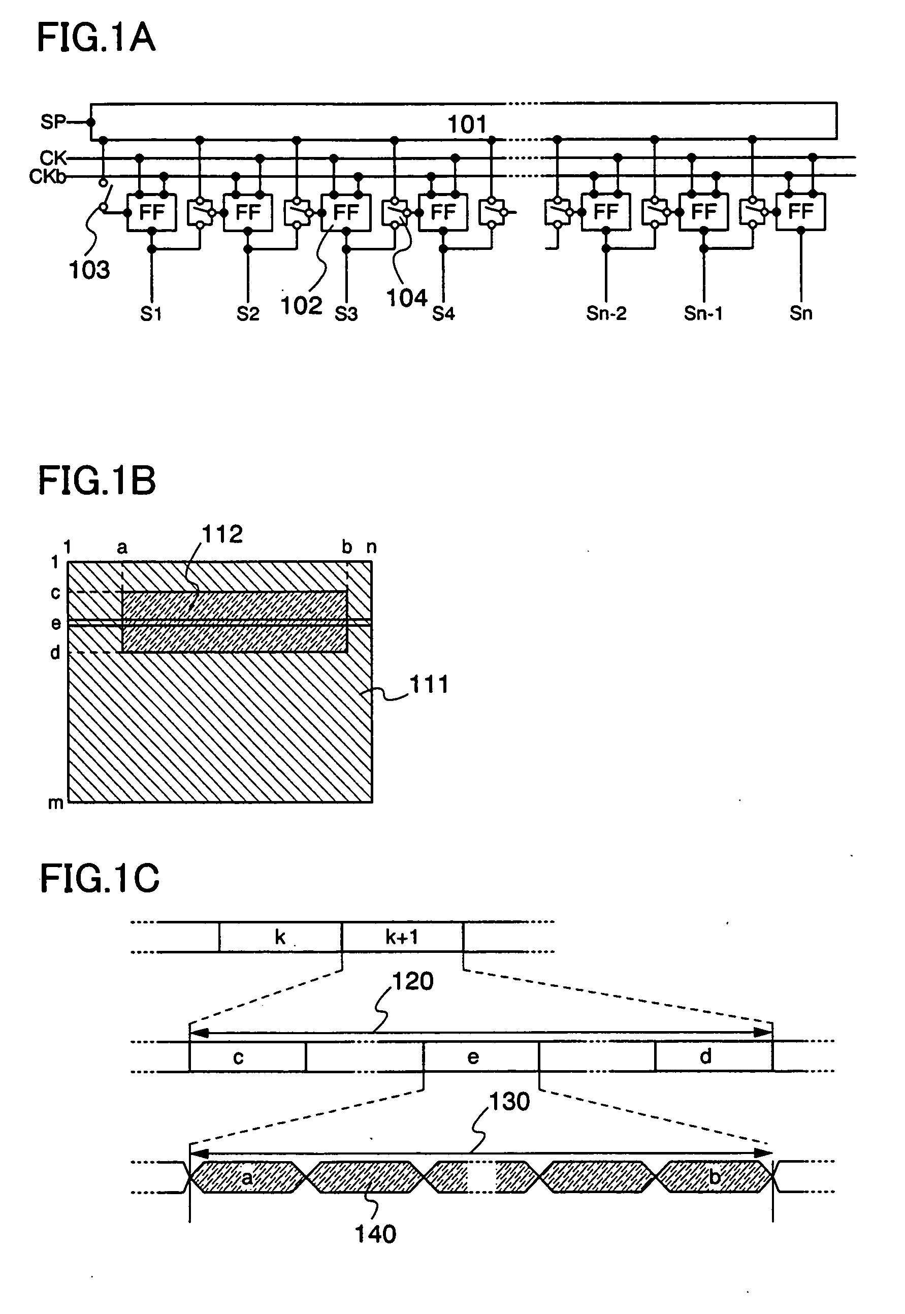
[0032] FIG. 1A shows a configuration of a scanning circuit as an embodiment mode of the invention. The scanning circuit has the same configuration as a conventional one in the respect that it employs a plurality of stages of D-flip-flops 102. However, it is additionally provided with a switch 104 for selecting an SP input / an prior stage input (hereinafter merely referred to as a switch 104) between each of the adjacent stages. Also, at an input terminal of the first stage, a switch 103 for selecting an SP input (hereinafter merely referred to as a switch 103) is provided.
[0033] The switch 103 provided at the input terminal of the D-flip-flop 102 of the first stage selects whether to permit an input of a start pulse (SP) to the first stage or not. The switch 104 provided between each of the adjacent stages of the D-flip-flops 102 selects whether to permit an input of SP or an output from the D-flip-flop 102 of a prior stage as an input to the D-flip-flop 102 of a subsequent stage, or...
embodiment mode 2
[0043] When a superimpose image overlaps with a background image, there is a case where the superimpose image is displayed simultaneously across a plurality of regions. In this embodiment mode, a driving method of a scanning circuit in this case is explained. As shown in FIGS. 6A and 6B, supposed here is the case where superimpose images 602 and 603 are displayed on a background image 601. The superimpose image 602 corresponds to a region surrounded by the a-th to b-th columns and the c-th to d-th rows, and the superimpose image 603 corresponds to a region surrounded by the f-th to g-th columns and the h-th to i-th rows.
[0044] When the background image 601 only is displayed at the k-th frame, and the superimpose images 602 and 603 are displayed at the (k+1)-th frame, video signals are updated in the region surrounded by the a-th to b-th columns and the c-th to d-th rows and in the region surrounded by the f-th to g-th columns and the h-th to i-th rows.
[0045] According to the inventi...
embodiment mode 3
[0053] Unlike Embodiment Modes 1 and 2, the invention can be also applied to the case where a superimpose image takes an intricate figure.
[0054] In FIGS. 12A to 12C, an example in the case where a superimpose image takes an intricate figure is shown. As shown in FIGS. 12A and 12B, a superimpose image 1202 is displayed on a background image 1201. At this time, the superimpose image 1202 takes a figure which is surrounded by a region, for example, having (a, f), (b, f), (b, e), (c, e), (c, f), (d, f), (d, g), (c, g), (c, h), (b, h), (b, g), and (a, g) as its tops.
[0055] In this case, when the background image 1201 only is displayed at the k-th frame and the superimpose image 1202 is displayed at the (k+1)-th frame, video signals are updated only in the e-th to h-th rows. Therefore, as shown in FIG. 12C, the scanning operation of a gate signal line at the (k+1)-th frame is performed only in the e-th to h-th rows. Furthermore, in the e-th to f-th rows, the video signals are updated only...
PUM
| Property | Measurement | Unit |
|---|---|---|
| size | aaaaa | aaaaa |
| operation frequency | aaaaa | aaaaa |
| power consumption | aaaaa | aaaaa |
Abstract
Description
Claims
Application Information