Turbojet electromechanical thrust reverser with synchronized locking devices

Active Publication Date: 2004-07-22
SAFRAN ELECTRICAL & POWER
View PDF6 Cites 28 Cited by
  • Summary
  • Abstract
  • Description
  • Claims
  • Application Information

AI Technical Summary

Benefits of technology

0006] The present invention thus seeks to mitigate such a drawback by proposing a thrust reverser that makes it possible to achieve real synchronization in th

Problems solved by technology

If one of these two orders is absent, then it is not

Method used


Image

  • Turbojet electromechanical thrust reverser with synchronized locking devices
  • Turbojet electromechanical thrust reverser with synchronized locking devices
  • Turbojet electromechanical thrust reverser with synchronized locking devices

Examples


Embodiment Construction

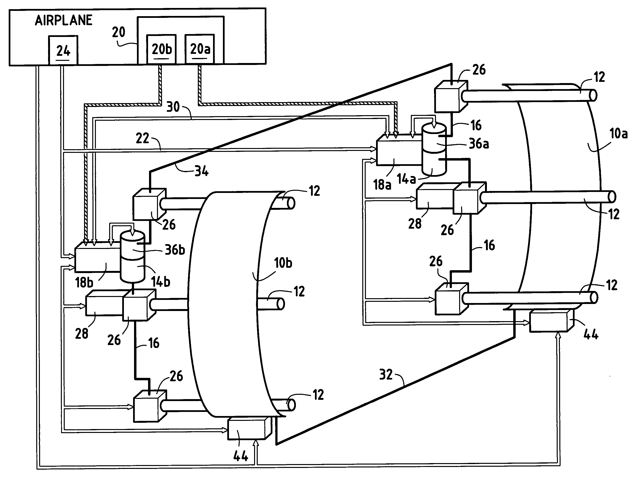
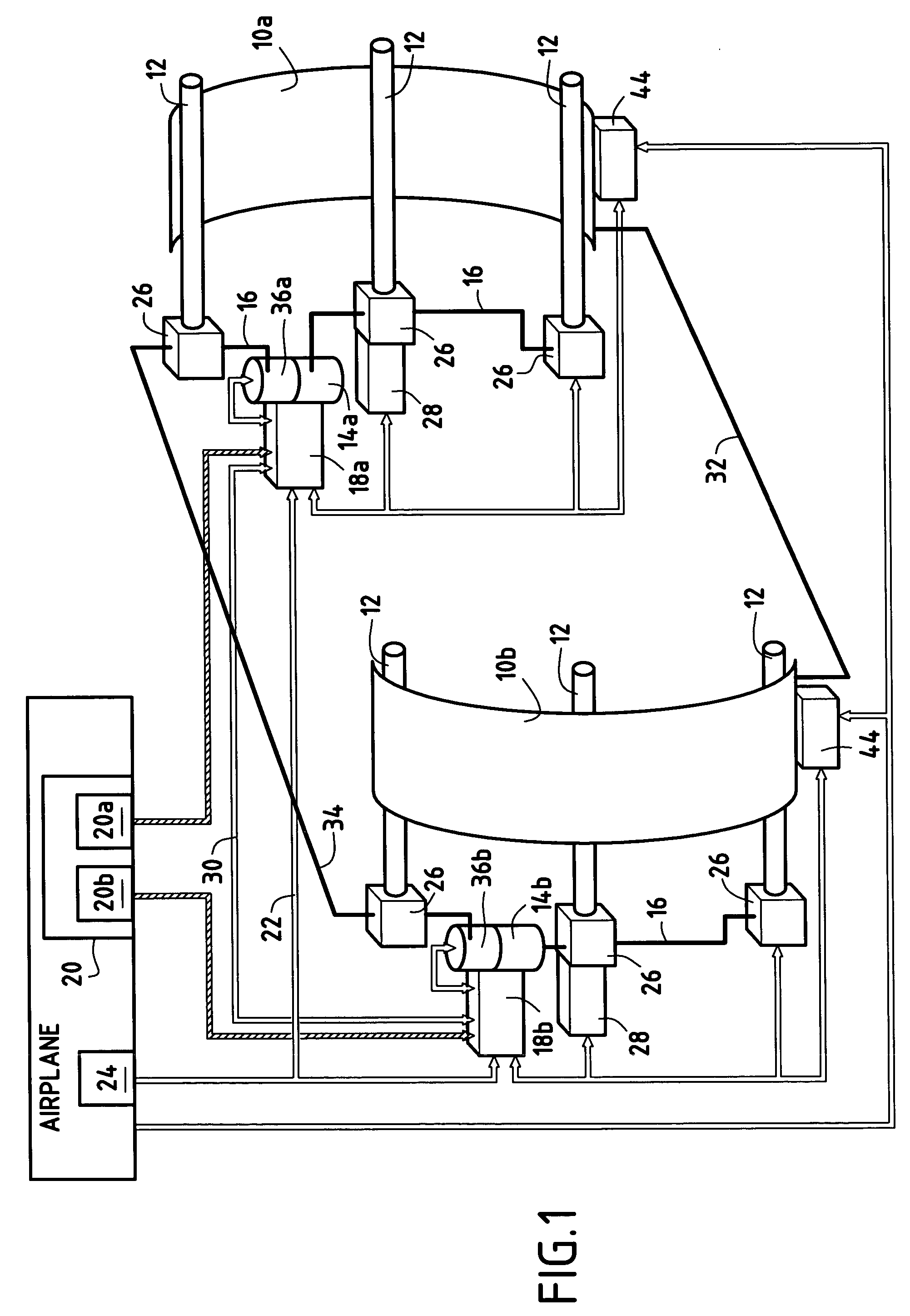
[0016] Reference is made initially to FIG. 1 which shows an embodiment of a thrust reverser of the invention.

[0017] The thrust reverser has two doors 10a, 10b each displaceable between a reverser open position and a reverser closed position under drive from at least one control actuator 12 (three actuators per door are shown in FIG. 1, a central actuator and two actuators positioned at respective lateral extremities of each door).

[0018] The reverser further comprises two electric motors 14a, 14b each controlling the displacement of one of the doors. These electric motors drive the control actuators 12 of each of the doors 10a, 10b via respective transmission shafts 16 that interconnect the control actuators for each of the doors.

[0019] Each electric motor 14a, 14b is mounted directly on an electronic control unit 18a, 18b which controls the entire displacement sequence of the corresponding door and regulates the speed of rotation of the electric motor. Each electronic control unit 1...


PUM


Abstract

A turbojet thrust reverser has two doors that are displaceable between a reverser open position and a reverser closed position, each door being controlled by a respective electronic control unit connected to a FADEC, and each door having a respective locking device for locking the position of the door associated therewith. Each locking device can be unlocked solely on receiving orders that come simultaneously from both electronic control units.

Description

[0001] A turbojet electromechanical thrust reverser with synchronized locking devices[0002] The present invention relates to the general field of thrust reversers for bypass turbojets. It relates more particularly to an electromechanical thrust reverser having at least two displaceable elements that co-operate, in the open position of the reverser, in producing thrust reversal, such as, for example, a thrust reverser having grids, doors, or shells.[0003] Thrust reversers fitted to bypass turbojets are well known in the field of aviation. They serve to increase the safety of an airplane by providing assistance in braking during landing. Thrust reversers are generally in the form of at least two moving elements such as sliding doors which are capable of being displaced relative to the pod of the turbojet by means of control actuators so that, when operating to provide thrust reversal, i.e. when the in the open position, they constitute an obstacle for a fraction of the gas coming from...

Claims


Application Information

Patent Timeline
IPC IPC(8): B64D33/00F02K1/54F02K1/76
CPCF05D2270/094F02K1/766
Inventor COLOTTE, BAPTISTECOURPIED, ALEXANDRECROIXMARIE, MARCJOLAND, PATRICKLE GOUELLEC, GILLESMICHAU, MARION
Owner SAFRAN ELECTRICAL & POWER
Why Eureka
Try Eureka