Conveying roller for a paper web, machines equipped therewith and methods of use

a technology of conveying roller and paper web, which is applied in the direction of thin material processing, article separation, and folding thin materials, etc., can solve the problems of paper jamming and stoppage of production, loss of vacuum and channel return to atmospheric pressure, and limited maximum air flow ra

Inactive Publication Date: 2004-08-19
MTC MACCINE TRASFORMAZIONE CARTA SRL
View PDF9 Cites 14 Cited by
  • Summary
  • Abstract
  • Description
  • Claims
  • Application Information

AI Technical Summary

Problems solved by technology

Furthermore, as soon as channel 102 is not more enabled for suction, even if there is a delay of the vacuum to disappear, then, in any case, the vacuum is lost and the channel returns to the atmospheric pressure.
A not efficient suction by the holes, on the other hand, can affect the successive operations of the machine causing paper jamming and stop of production.
In any case, the maximum air flow rate is limited.
to limit the length of the roller and then the volume of the chambers in it; this causes a subsequent limitation in the maximum width of the paper that can be processed and then reduces productivity of the machines that have such rollers;
The sealing ability of the holes, however is limited to the contact with a web of paper and with a certain pressure, whereby this type of roller is unsuitable for applications with sheets of paper.

Method used


Image

  • Conveying roller for a paper web, machines equipped therewith and methods of use
  • Conveying roller for a paper web, machines equipped therewith and methods of use
  • Conveying roller for a paper web, machines equipped therewith and methods of use

Examples


Embodiment Construction

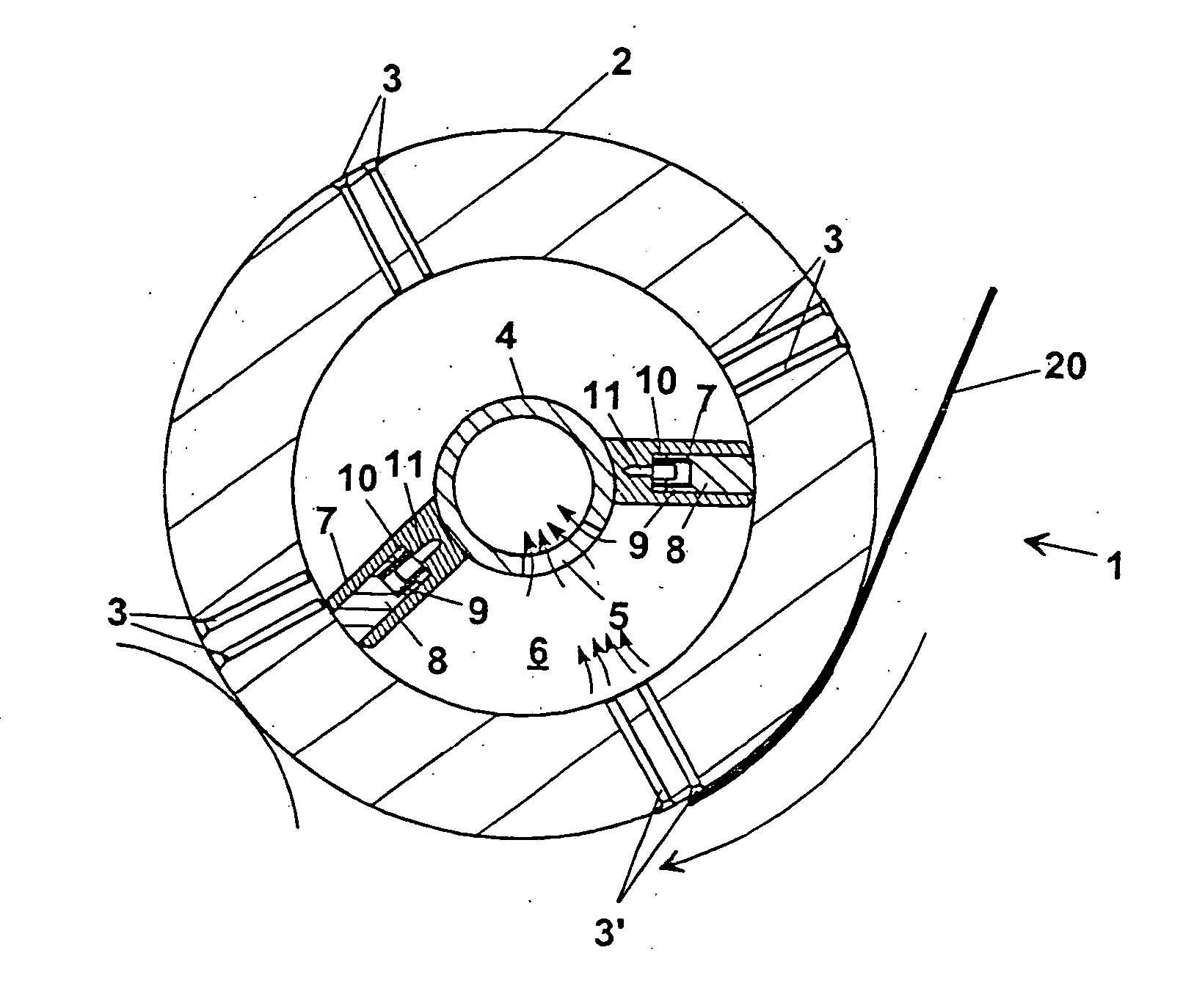
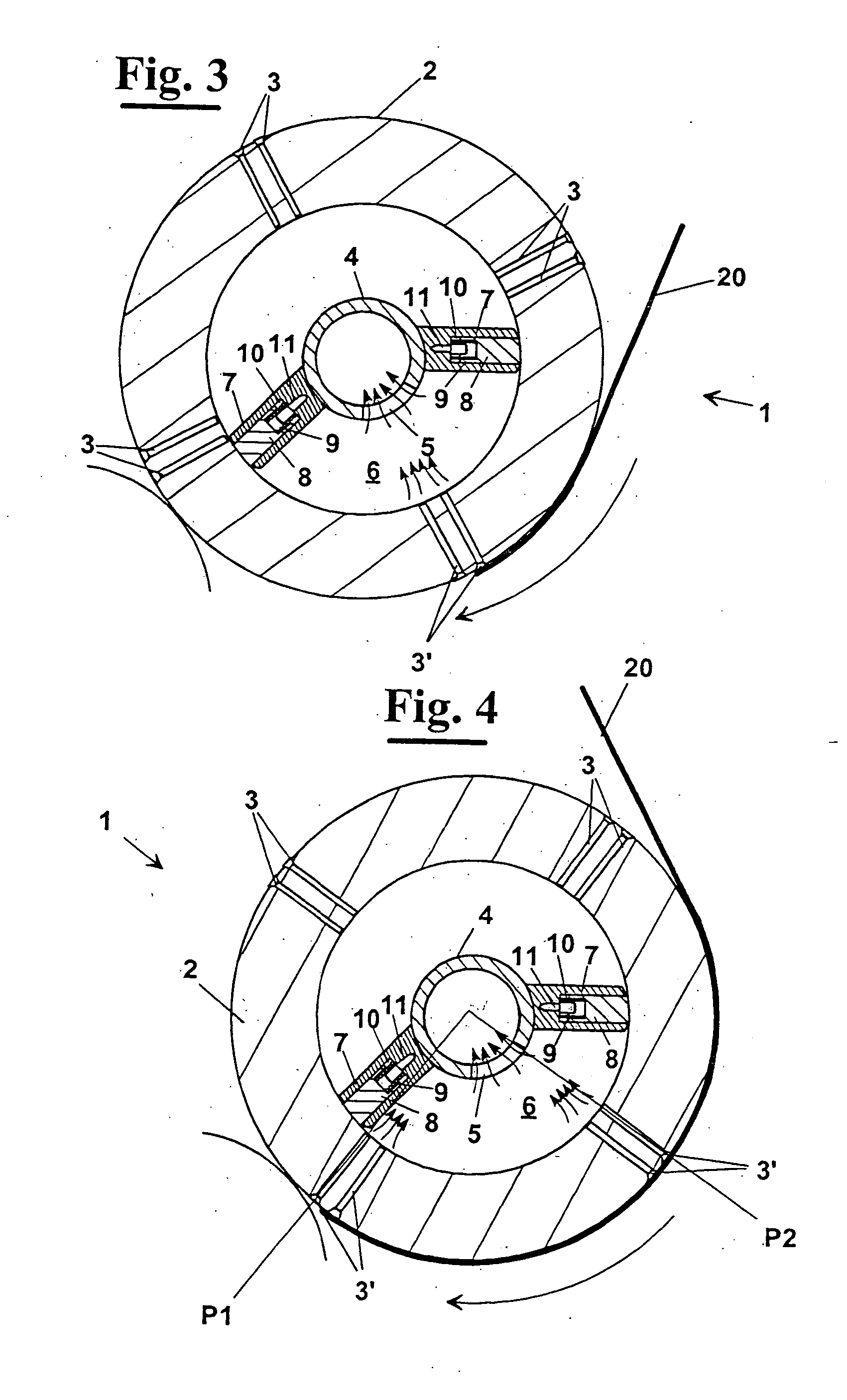
[0036] In FIGS. 3 and 4 a cross sectional view is shown of. a roller 1 used for conveying a web or sheet of paper 20 for paper converting machines, for example, a rewinding machine, a winding machine, an interfolding machine. It comprises a first outer cylindrical tubular body 2, equipped with a plurality of radial holes 3 arranged according to substantially longitudinal rows, capable of rotating with respect to a second inner fixed body 4, co-axial to the former and connected to a suction system not shown. The second body 4, which as shown in the embodiments of FIGS. 3 and 4 has tubular cylindrical geometry like first body 2, has a plurality of apertures 5 and two radial boards 7 at opposite sides with respect to apertures 5.

[0037] The inner surface of first cylindrical tubular body 2, radial boards 7 and the external surface of second tubular body 4 define a suction chamber 6 that, during the relative rotation of the two bodies, brings selectively in communication some rows of hol...


PUM

PropertyMeasurementUnit
lengthaaaaaaaaaa
angleaaaaaaaaaa
atmospheric pressureaaaaaaaaaa

Abstract

The roller (1) is used for conveying a web or sheet of paper (20) in paper converting machines, for example, a rewinding, a winding, an interfolding machine. It comprises a first outer cylindrical tubular body (2) equipped with a plurality of radial holes (3), arranged according to substantially longitudinal rows, capable of rotating with respect to a second inner fixed body (4) co-axial to it and connected to a suction system. The second body (4) has tubular cylindrical geometry like the first body (2) and has a plurality of apertures (5) and two radial boards (7) arranged at opposite sides with respect to the apertures (5). The inner surface of the first cylindrical tubular body (2), together with the radial boards (7) and to the external surface of the second tubular body (4), define a suction chamber (6) that brings selectively in communication selected rows of holes (3) of the first cylindrical tubular body (2) with the apertures (5) of the second tubular body (4) and then with the suction system of the machine during the relative rotation of the two bodies. Therefore, a web or sheet of paper (20) adheres to the external surface of the first body (2) only in the portion P1P2 of surface set between the rows of holes (3') that communicates with the suction chamber (FIG. 4).

Description

[0001] The present invention relates to the field of machines for converting paper and similar products, and in particular it relates to a paper conveying roller for machines working in this field such as in particular winding, rewinding, interfolding machines.[0002] In particular, the invention relates to a paper conveying roller having circumferentially a plurality of holes which, connected to a vacuum system, allow the sheet or web of paper to adhere on their surface.DESCRIPTION OF THE PRIOR ART[0003] As known, many machines used in the paper converting field, for example rewinding and interfolding machines, are equipped on the surface of their rollers with systems for capturing the web or the sheet of processed paper, in certain operative phases, in order to cause the paper to follow a predetermined path.[0004] In particular, such systems are used to provide the main operations of cutting the paper, of transferring it quickly from a roller to another, of final folding the paper ...

Claims


Application Information

Patent Timeline
Patent Type & Authority Applications(United States)
IPC IPC(8): B65H27/00
CPCB65H2406/3614B65H27/00B65H45/24B65H45/28
Inventor DEMATTEIS, ALESSANDRO
Owner MTC MACCINE TRASFORMAZIONE CARTA SRL
Why Eureka
Try Eureka