Flow measuring device

a technology of flow measurement and measuring device, which is applied in the direction of liquid/fluent solid measurement, volume/mass flow by differential pressure, instruments, etc., can solve the problem of relatively high cost involved, and achieve the effect of reducing complexity

Inactive Publication Date: 2004-10-07
FESTO AG & CO KG
View PDF6 Cites 9 Cited by
  • Summary
  • Abstract
  • Description
  • Claims
  • Application Information

AI Technical Summary

Benefits of technology

[0005] One object of the present invention is to suggest measures with which adaptation to different measurement eventualities may be taken into account with reduced complexity.
[0007] It is in this manner that different measuring needs of the user may be taken into account, because selectively a duct insert which has the desired specification may be fitted in the housing of the flow measuring device. The housing itself and frequently the flow ascertaining means and the flow ascertaining means as well may as a rule be kept irrespectively of the actually employed duct insert so that a substantial economy in costs may be expected. The tapping ducts extending between the principal flow duct and the flow ascertaining means are divided into housing and insert duct sections, and by having suitably designed interfaces on the mutually facing inner and outer faces of the socket and of the duct insert a coordinated fluid linking is ensured irrespectively of the actually employed duct insert. The design, separate from that of the housing, of the duct insert also facilitates the manufacture of the frequently complex features needed for the production of the desired pressure drop.
[0010] To the extent it is necessary owing to the design of the interfaces, suitable positioning means may be provided on the housing and on the duct insert, which set a certain angular position of the duct insert in relation to the socket of the housing and accordingly favor installation without any danger of confusion.
[0011] A high degree of accuracy combined with a relatively low dependency on the type of flow impact owing to the pressure medium may be obtained if the respective tapping duct opens into the principal flow duct at a plurality of tapping openings distributed about the periphery of the duct, such tapping openings communicating jointly with an annular groove formed at the outer periphery of the duct insert. The pressure signals produced are accordingly averaged so that irregularities in the flow conductance in the tapping cross sections, which result from the type and direction of the impacting flow, are minimized.

Problems solved by technology

The costs involved here are relatively high.

Method used


Image

  • Flow measuring device
  • Flow measuring device
  • Flow measuring device

Examples


Embodiment Construction

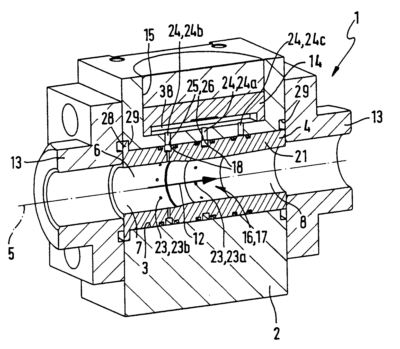
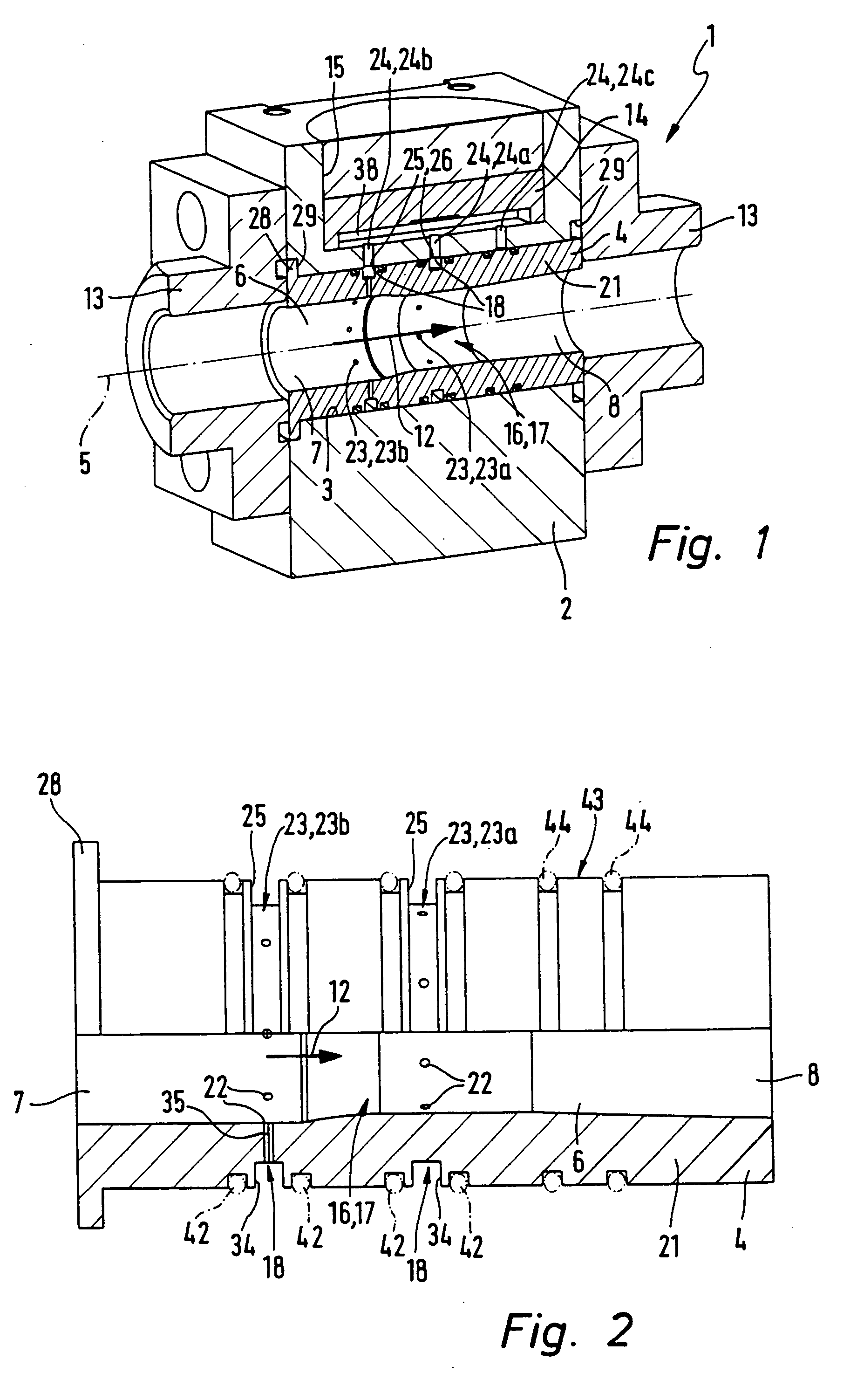
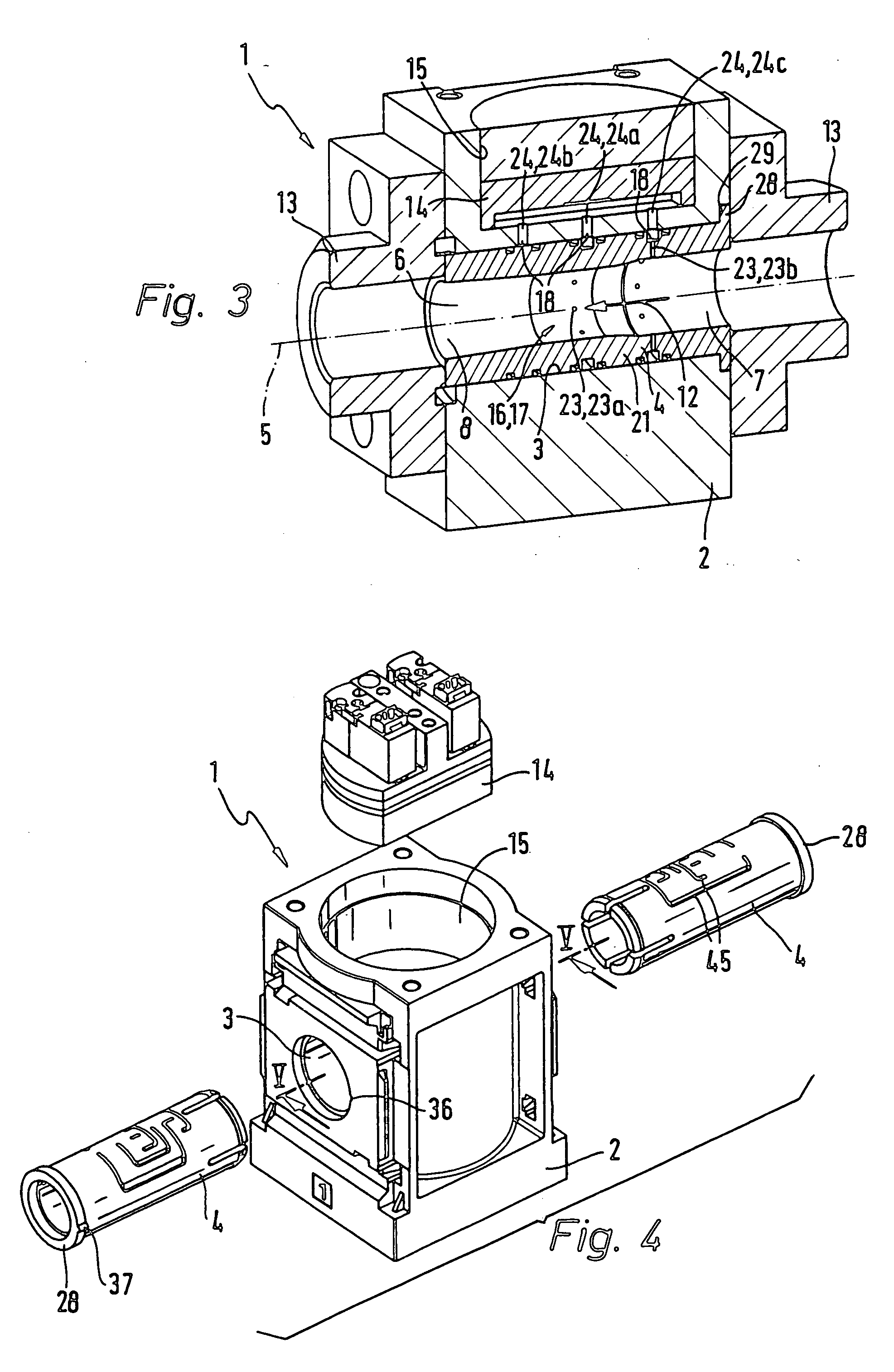
[0020] The flow measuring devices generally referenced 1 each possess a housing 2, which may be more particularly designed like a block and have a preferably circularly cylindrical socket 3 extending through it. In the socket 3 a sleeve-like component is inserted which is termed a duct insert and whose external geometry is complementary to the socket 3. This component defines a principal flow duct 6 extending through the housing 2 in one longitudinal direction 5.

[0021] The principal flow duct 6 possesses an inlet 7 at one end and an outlet 8 at the other end. At the inlet 7 a pressure medium may be supplied to the principal flow duct 6, which after flowing through the principal flow duct 6 emerges again at the outlet 8. The flow direction through the principal flow duct 6 is indicated by an arrow at 12.

[0022] In the case of the working example of FIGS. 1 through 3 the housing carries two connection bodies 13 on it in an extension of the duct insert 4 at either end, such bodies rende...


PUM


Abstract

A flow measuring device comprising a housing in which a principal flow duct extends in which pressure drop producing means are located responsible for a pressure drop of the pressure flowing through and in the wall of the duct the tapping openings of a plurality of tapping ducts connected with a flow ascertaining means arranged in the housing are provided. The principal flow duct, including the pressure drop producing means and the tapping openings, is a component of a sleeve-like duct insert inserted into the housing coaxially. The inner face of the socket and the outer face of the duct insert are so designed in the form of interfaces that during assembly of the duct insert a correctly coordinated fluid connection of the duct sections in the housing and in the inserts of the tapping ducts is ensured.

Description

BACKGROUND OF THE INVENTION.[0001] The invention relates to a flow measuring device comprising a housing in which a principal flow duct extends in which a pressure drop producing means producing a pressure drop in the medium flowing through is located and on whose duct wall the tapping openings of a plurality of tapping ducts connected with a flow ascertaining means arranged in or on the housing, are provided.THE PRIOR ART.[0002] A flow measuring device disclosed in the German patent publication (utility model) 20,208,716 comprises a tubular housing, in which a principal flow duct is formed in the course of which there is a laminar flow element, which comprises a plurality of capillary ducts causing a pressure drop in fluid flowing through them. Two tapping ducts opening at a distance apart from each other upstream from and downstream from the laminar flow element are connected with a flow ascertaining means mounted on the housing and define a gage duct, in which owing to a pressure...

Claims


Application Information

Patent Timeline
Patent Type & Authority Applications(United States)
IPC IPC(8): G01F1/36G01F1/44
CPCG01F1/36G01F1/44
Inventor NESTLE, VOLKERSCHULZ, WINFRIED
Owner FESTO AG & CO KG
Why Eureka
Try Eureka