Centralized traffic signal preemption system and method of use

a traffic signal and preemption system technology, applied in the direction of road vehicle traffic control, traffic signal control, control of traffic signals, etc., can solve the problems of inability to control traffic signals

Inactive Publication Date: 2004-10-07
LOCKHEED MARTIN CORP
View PDF26 Cites 72 Cited by
  • Summary
  • Abstract
  • Description
  • Claims
  • Application Information

AI Technical Summary

Problems solved by technology

Each of these technologies have unique problems such as maintenance issues for under the roadway systems or passing traffic can interfere with infrared signals and ultrasonic signals.
Obstructions may also interfere with this technology.
Other problems include determining the arrival time of an EV at a particular intersection.
Radio control systems utilize signal strength measurements to anticipate arrival times of EVs at intersections; however, preemption of traffic signals too early can lead to impatient drivers proceeding through an intersection causing potential accident risks.
Additionally, preemption too late may cause undesirable delays in the EVs progress.
In this case, the type of preemption equipment in the EV may be incompatible with traffic control systems installed at intersections.
This, of course, poses many logistical problems and may also attribute to slow response times.
Another limitation of the above systems includes the lack of a centralized traffic management system that is capable of coordinating essentially all EVs and traffic light preemption decisions within a broader geographical area, which may include multiple jurisdictions, multiple fleet management systems, or multiple traffic management systems.
Since, generally, all of the above systems communicate only between the EV and a proximate traffic light controller that is local to an intersection, comprehensive coordination of traffic lights along an entire route cannot be provided.
Nor, in these systems, can coordination of complementing emergency vehicles (e.g., police and fire trucks together) for a given emergency or similar situation be provided.

Method used


Image

  • Centralized traffic signal preemption system and method of use
  • Centralized traffic signal preemption system and method of use
  • Centralized traffic signal preemption system and method of use

Examples


Embodiment Construction

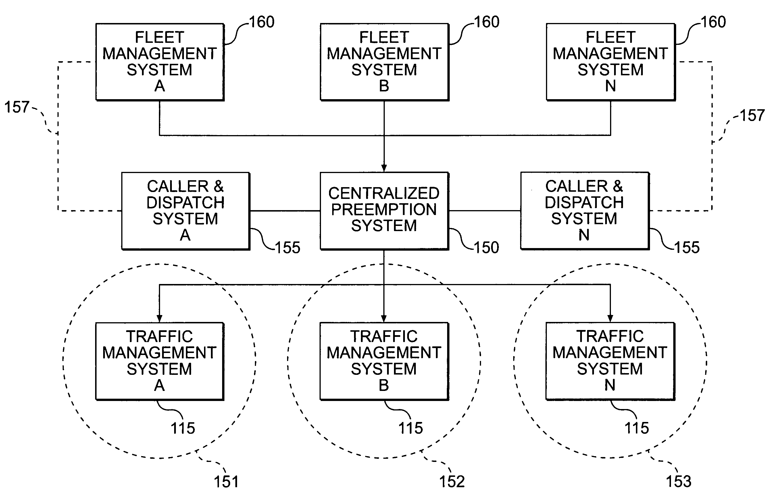
[0044] The present invention is directed to a system and method that provides centralized preemption of traffic signals based on vehicle activity and predefined policy rules. In this method and system of the present invention, centralized preemption and coordination of multiple traffic management systems (TMS) is provided within one or more jurisdictions. Further, this method and system provides for centralized preemption of diverse fleets such as, for example, police, fire, ambulance, rescue, buses, and special convoys. This provides substantial improvement in delivering emergency type services and centralized preemption to communities using existing deployed traffic control systems. This may involve one or more jurisdictions such as counties, cities, states, municipalities, etc.

Embodiments of the Present Invention

[0045] FIG. 3 represents an overall view of an embodiment of the present invention. A Centralized Preemption System (CPS) 150 is shown to be in communication with Fleet M...


PUM


Abstract

A system and method of centralizing traffic signal preemption for roadway emergency operations provides for increased accuracy and coordination of emergency response vehicles along an emergency route. A centralized preemption system receives status and location information, e.g., GPS, from emergency vehicles via fleet management systems or dispatch centers. As an emergency route is determined and projected in real-time, predetermined policies are applied to create an overall preemption plan of traffic lights at intersections along an anticipated route. The preemption plan results in preemption directives being transmitted to traffic management systems that are controlling traffic signal controllers at intersections along the route. The centralized preemption system may coordinate among many traffic management systems that provides for a much larger preemption service area including multiple jurisdictions.

Description

[0001] 1. Field of the Invention[0002] The present invention generally relates to a traffic signal preemption system and, more particularly, a system and method that provides centralized preemption of traffic signals based on vehicle activity across diverse systems.[0003] 2. Background Description[0004] Traffic preemption control systems have been utilized in present day localities to provide preemptive control of traffic signals and to provide traffic flow control for various types of vehicles such as ambulances, police cars, fire trucks, buses, special convoys, and the like, and denoted as emergency vehicles (EV) hereinafter. The term emergency vehicle (EV) is not limiting to only emergency vehicles, but includes any vehicle for which traffic preemption is provided.[0005] In general, traffic signal preemption is a process that allows emergency vehicles to temporarily change the timing plans of traffic signals so that the emergency vehicles do not have to wait for a red light and a...

Claims


Application Information

Patent Timeline
Patent Type & Authority Applications(United States)
IPC IPC(8): G08G1/087G08G1/123
CPCG08G1/087G08G1/20
Inventor BROOKE, O'NEIL
Owner LOCKHEED MARTIN CORP
Why Eureka
Try Eureka