Image recording apparatus

Inactive Publication Date: 2004-10-07
RISO KAGAKU CORP
View PDF3 Cites 29 Cited by
  • Summary
  • Abstract
  • Description
  • Claims
  • Application Information

AI Technical Summary

Problems solved by technology

Actually, however, since an ejection cycle of the ink is determined based on the essential capability of the recording head, it is difficult to reduce the interval beyond the capability.
The quality of an image obtained by the ink dots is deteriorated when an ejection defect is generated due to clogging of the nozzles or the like.
Therefore, the detection

Method used


Image

  • Image recording apparatus
  • Image recording apparatus
  • Image recording apparatus

Examples


Embodiment Construction

[0173] An image recording apparatus 10 according to a second embodiment will now be described with reference to FIGS. 7 and 8. It is to be noted that the constituent members similar to those in the image recording apparatus 10 according to the first embodiment are denoted by reference numerals designating the same constituent members of this image recording apparatus 10 in this embodiment, thereby omitting the detailed explanation. The image recording apparatus 10 according to the second embodiment has only one recording head 20 as different from the first embodiment. Furthermore, in the image recording apparatus 10 according to this embodiment, the operation of the controller 80 in the ink ejection state inspection is different.

[0174] The image recording apparatus 10 according to this embodiment is different from the first embodiment, and the nozzles in the same nozzle column is divided into groups. Moreover, the ejection timings of these groups are different from each other. More ...


PUM


Abstract

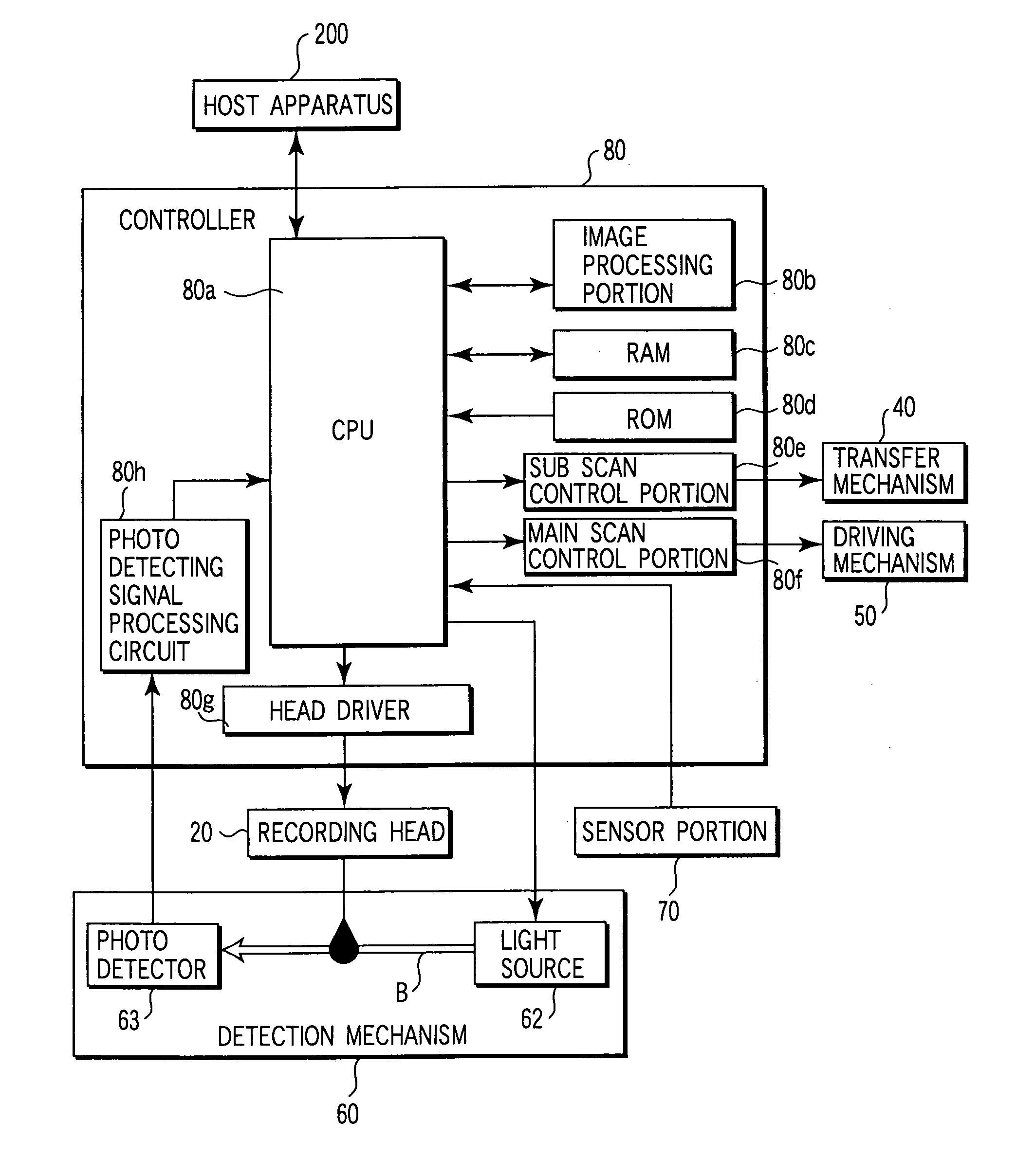
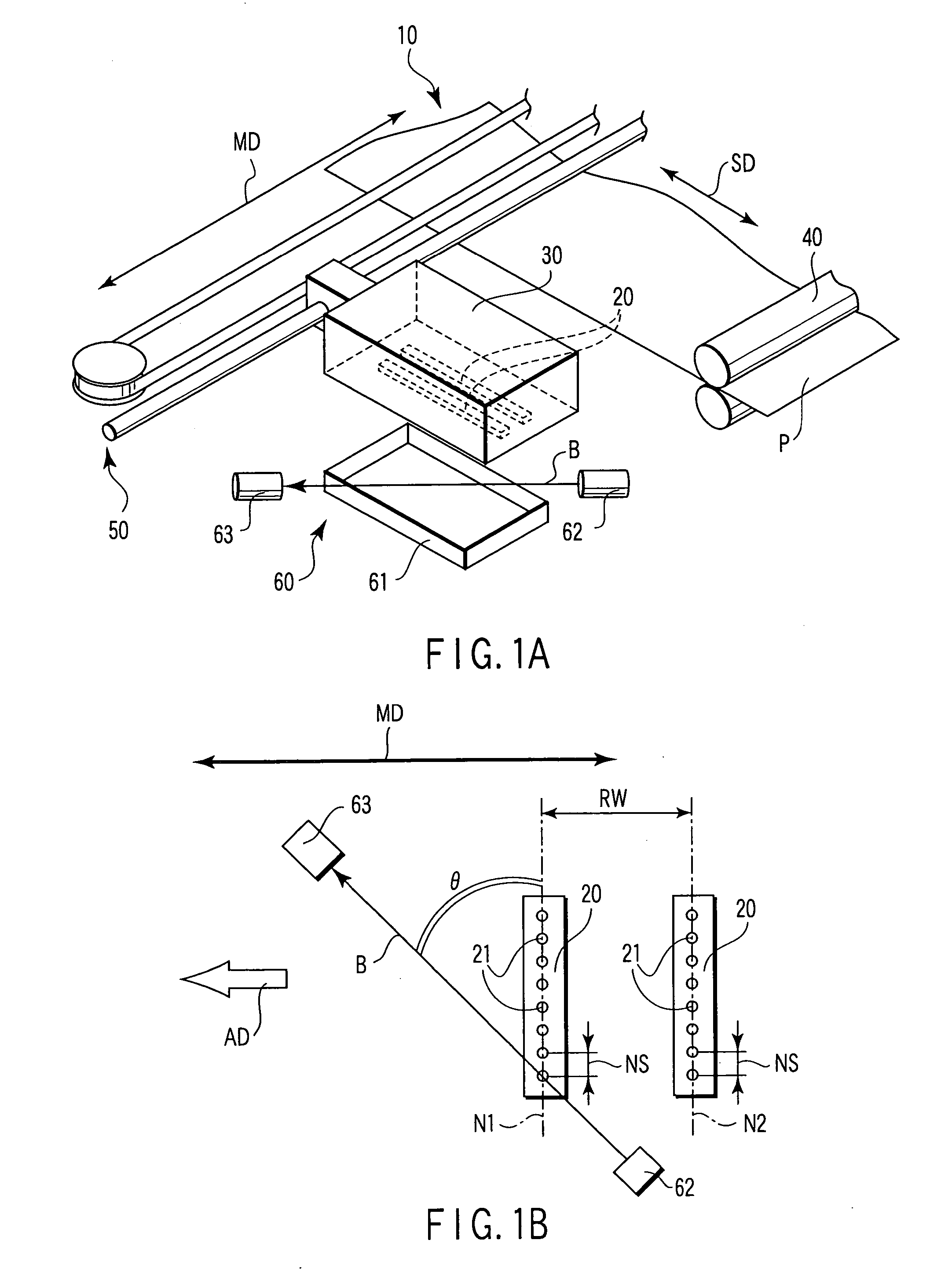
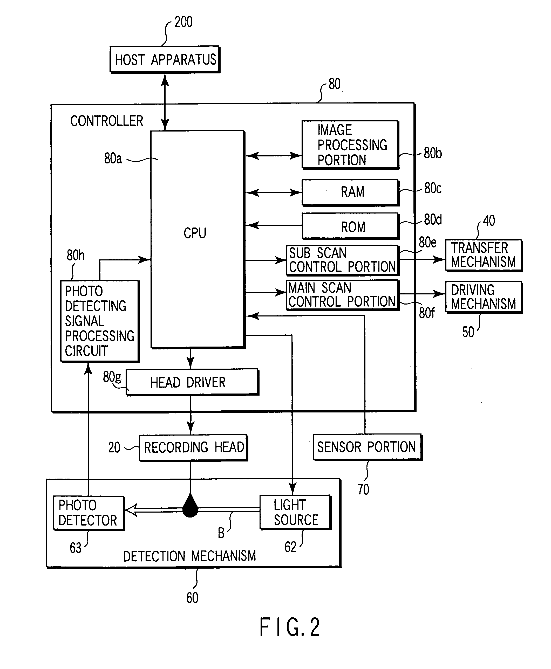
An image recording apparatus includes a recording head having a plurality of nozzles, a carriage, a transfer mechanism, a driving mechanism, a detection mechanism which optically detects an ink ejection state, and a controller. The plural nozzles are divided into a plurality of nozzle groups. The controller makes an ejection timing of each of the nozzle groups different from that of any other nozzle group. The shifting time of the timing of each of the nozzle group is shorter than an ejection cycle in image recording of each group.

Description

[0001] This is a Continuation Application of PCT Application No. PCT / JP02 / 10652, filed Oct. 15, 2002, which was not published under PCT Article 21(2) in English.[0002] This application is based upon and claims the benefit of priority from prior Japanese Patent Application No. 2001-316967, filed Oct. 15, 2001, the entire contents of which are incorporated herein by reference.[0003] 1. Field of the Invention[0004] The present invention relates to an image recording apparatus having a detection mechanism which detects an ejection state of a nozzle.[0005] 2. Description of the Related Art[0006] An ink jet type image recording apparatus records an image by ejecting an ink to a recording medium. The image recording apparatus has a recording head which ejects an ink to the recording medium, a carriage which holds the recording head, transferring means for transferring the recording medium, and carriage driving means for moving the carriage in a direction (main scan direction) orthogonal to...

Claims


Application Information

Patent Timeline
IPC IPC(8): B41J2/045B41J2/05B41J2/125B41J2/15B41J2/165
CPCB41J2/0451B41J2/04561B41J2/04573B41J2/04581B41J2/04586B41J2/125B41J2/15B41J2/16579B41J2202/20
Inventor ARUGA, TOSHINAO
Owner RISO KAGAKU CORP
Why Eureka
Try Eureka