Fingertip suture-cutting apparatus

Inactive Publication Date: 2004-11-25
MIKLOS JOHN R
View PDF7 Cites 30 Cited by
  • Summary
  • Abstract
  • Description
  • Claims
  • Application Information

AI Technical Summary

Benefits of technology

0010] The present invention comprises a fingertip mountable suture cutter apparatus with a housing of generally cylindrical shape. The suture cutter apparatus has a distalmost end of a fingertip-enclosing hemispherical shape and an opened fingertip receiving proximalmost end. The housing has a curvilinear lowermost body portion and an uppermost opened portion. The uppermost portion of the housing of

Problems solved by technology

This is often hazardous as it may require reaching across the patient for those scissors and such scissors may also inadvertently cut neighboring tissue.
Such suture cutter or thread cutting arrangements, while helpful sometimes are not very practical in actual use.
This arrangement, however, appears to require even more careful manipulation than a pair of scissors.
U.S. Pat. No. 3,990,144 to Schwartz presents a suture cutter and removal means which might be difficult to manipulate in a surgical setti

Method used


Image

  • Fingertip suture-cutting apparatus
  • Fingertip suture-cutting apparatus
  • Fingertip suture-cutting apparatus

Examples


Embodiment Construction

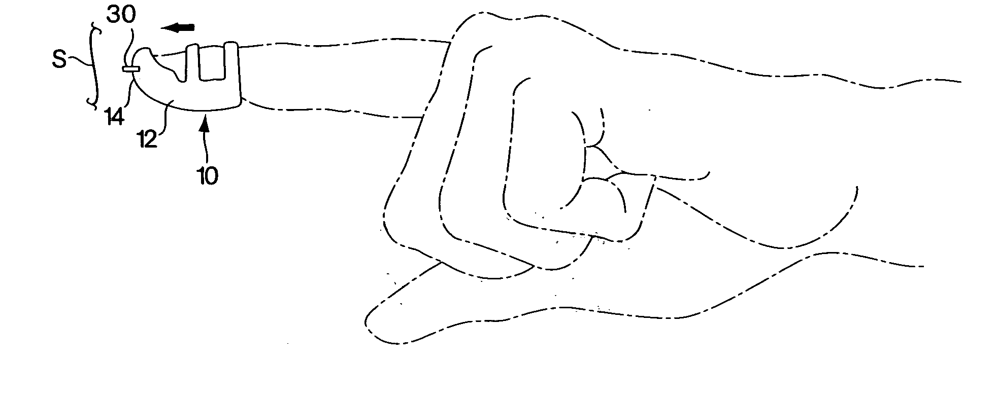
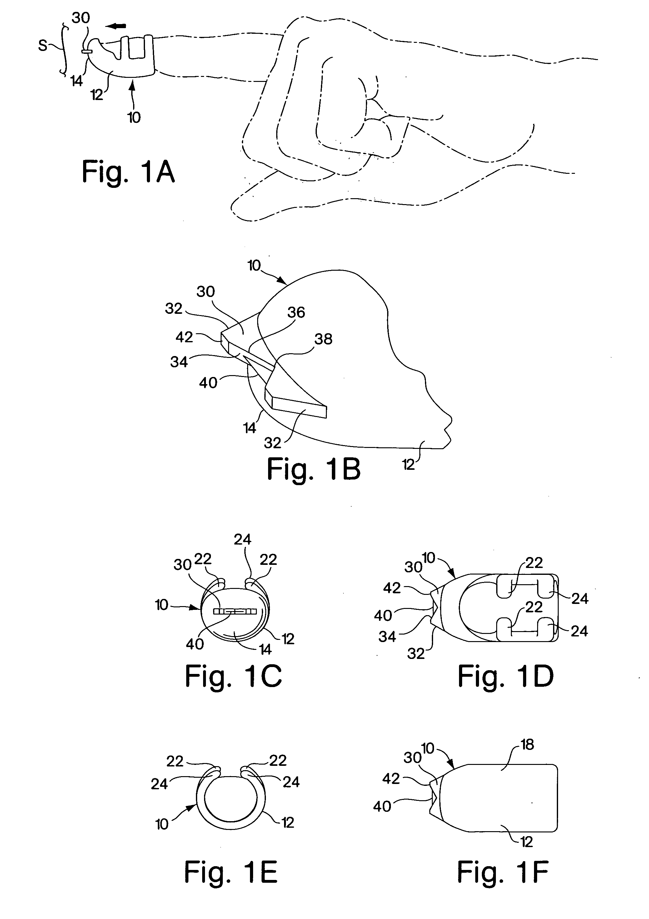
[0035] Referring now to the drawings in detail, and particularly to FIGS. 1A and 1B, there is shown the present invention which comprises a fingertip mountable suture cutter apparatus 10 with a housing 12 of generally cylindrical shape. The suture cutter apparatus 10 has a distalmost end 14 of a fingertip-enclosing hemispherical shape and an opened fingertip receiving proximalmost end 16, as represented in figures 1A, 1B and 1E. The housing 12 has an elongated curvilinear lowermost body portion 18, as represented in FIG. 1F, and an uppermost opened portion 20, as represented in FIGS. 1A, 1C, 1D and 1E. The uppermost portion 20 of the housing 12 of the suture cutter apparatus 10 is defined by a first pair and a second pair of slightly flexible, arcuately disposed ribs 22 and 24. The arcuate ribs 22 and 24, a first and second on each lateral side of the housing 12, are spaced longitudinally apart and their tips are spaced transversely apart, as represented in FIGS. 1A and 1D. The spac...


PUM

PropertyMeasurementUnit
Angleaaaaaaaaaa
Flexibilityaaaaaaaaaa
Areaaaaaaaaaaa

Abstract

A suture cutting apparatus for cutting a suture during a surgical procedure. The suture cutting apparatus is arranged for receipt on a fingertip. The apparatus comprises a hollow, generally cylindrically shaped housing, the housing has a first or distal end and a second or proximal end. A razor blade is supported on the distal end of the housing. The first or distal end of the housing is closed by a hemispherically shaped enclosure. The hemispherically shaped enclosure has a flange on a distal portion thereof to support the blade. The flange has a V-shaped notch disposed thereon, and the blade is arranged in the notch.

Description

BACKGROUND OF THE INVENTION[0001] 1. Field of the Invention[0002] The present invention relates to surgical devices and more particularly to suture cutter arrangements to be worn by surgeons during medical procedures.[0003] 2. Prior Art[0004] Most surgical procedures require the suturing of tissue during or subsequent to that procedure. Cutting of such sutures is typically done with a pair of scissors which is passed from the scrub nurse to the surgical assistant or to the surgeon directly. In cutting the suture, often those scissors must be steadied with a second hand of the surgeon, or await the correct angle to approach the suture by those scissors. This is often hazardous as it may require reaching across the patient for those scissors and such scissors may also inadvertently cut neighboring tissue.[0005] The possibility of a more manipulable and safer alternative to scissors is thus very desirable.[0006] Thread or suture cutting arrangements have been proposed over the past few...

Claims


Application Information

Patent Timeline
IPC IPC(8): A61B17/04A61B19/04B26B27/00
CPCA61B17/0467A61B42/20Y10T83/04B26B27/007
Inventor MIKLOS, JOHN R.
Owner MIKLOS JOHN R
Why Eureka
Try Eureka