Eureka AIR delivers breakthrough ideas for toughest innovation challenges, trusted by R&D personnel around the world.

High efficiency dehumidifiers and combined dehumidifying/air-conditioning systems

a technology of dehumidifier and air conditioner, which is applied in the direction of cooling fluid circulation, lighting and heating apparatus, domestic heating, etc., can solve the problems of low air conditioner efficiency, high moisture content of cooled, and inability to work well

Active Publication Date: 2004-12-30
DUCOOL
View PDF3 Cites 47 Cited by
  • Summary
  • Abstract
  • Description
  • Claims
  • Application Information

AI Technical Summary

Benefits of technology

[0009] Optionally, the elements are mounted on the blades of a propeller or windmill, which is caused to turn by the incoming air current, and the blades dip in and out of the reservoir as the windmill turns. This design has the advantage that if the air streaming into the dehumidifier speeds up or slows down, and the desiccant consequently gets saturated more quickly or less quickly, then the moisture laden desiccant is automatically replaced more quickly or less quickly, corresponding to the replacement rate that is needed.
[0014] Using a wheel, belt, or similar mechanical system to circulate desiccant out of and into the reservoir has some advantages over the prior art of spraying, dripping, or wicking the desiccant from the reservoir. Wicking, as described in unpublished PCT Application PCT / IL01 / 00374, is slower than the other methods, since the dehumidification rate or regenerating rate is limited by the speed at which water flows down the wick into the reservoir in the dehumidifying section, and up the wick from the reservoir in the regenerating section. Dripping requires some power to lift the desiccant up to the point where it is dripped, and requires special pumps to pump the (generally corrosive) desiccant.
[0019] Although prior art systems using evaporation for cooling share this feature of low power requirements, they introduce into the air-conditioned environment air that has higher moisture content than the ambient air. In some embodiments of the invention, the moist cooled air is not released into the air-conditioned environment, but is only used in heat exchangers to cool other air directly (or indirectly by cooling desiccant), and then released into the ambient environment. Thus, the advantage of low power requirements can be obtained, without the disadvantage of introducing moist air into the air-conditioned environment.
[0066] Optionally, there is a sensor which senses the amount of moisture absorbed by the desiccant in at least one of the at least one dehumidifying section elements, and a controller which causes said dehumidifying section element to move or to move faster when the absorbed moisture exceeds a given level.
[0080] Optionally, there is a sensor which senses the amount of moisture absorbed by the desiccant in at least one of the at least one regenerating section elements, and a controller which causes said regenerating section element to move or to move faster when the absorbed moisture falls below a given level.

Problems solved by technology

The air must then be cooled even more than if it had remained at the outside temperature, which also lowers the efficiency of the air conditioner.
The disadvantages of evaporative cooling are that the air that is cooled has a higher moisture content than the ambient air, and the method doesn't work well at high ambient humidity.
Nevertheless, evaporative cooling is often used to cool open environments, for example stockyards, where low humidity is not so important, ambient humidity is not too high, and low power consumption is important.

Method used


Image

  • High efficiency dehumidifiers and combined dehumidifying/air-conditioning systems
  • High efficiency dehumidifiers and combined dehumidifying/air-conditioning systems
  • High efficiency dehumidifiers and combined dehumidifying/air-conditioning systems

Examples


Embodiment Construction

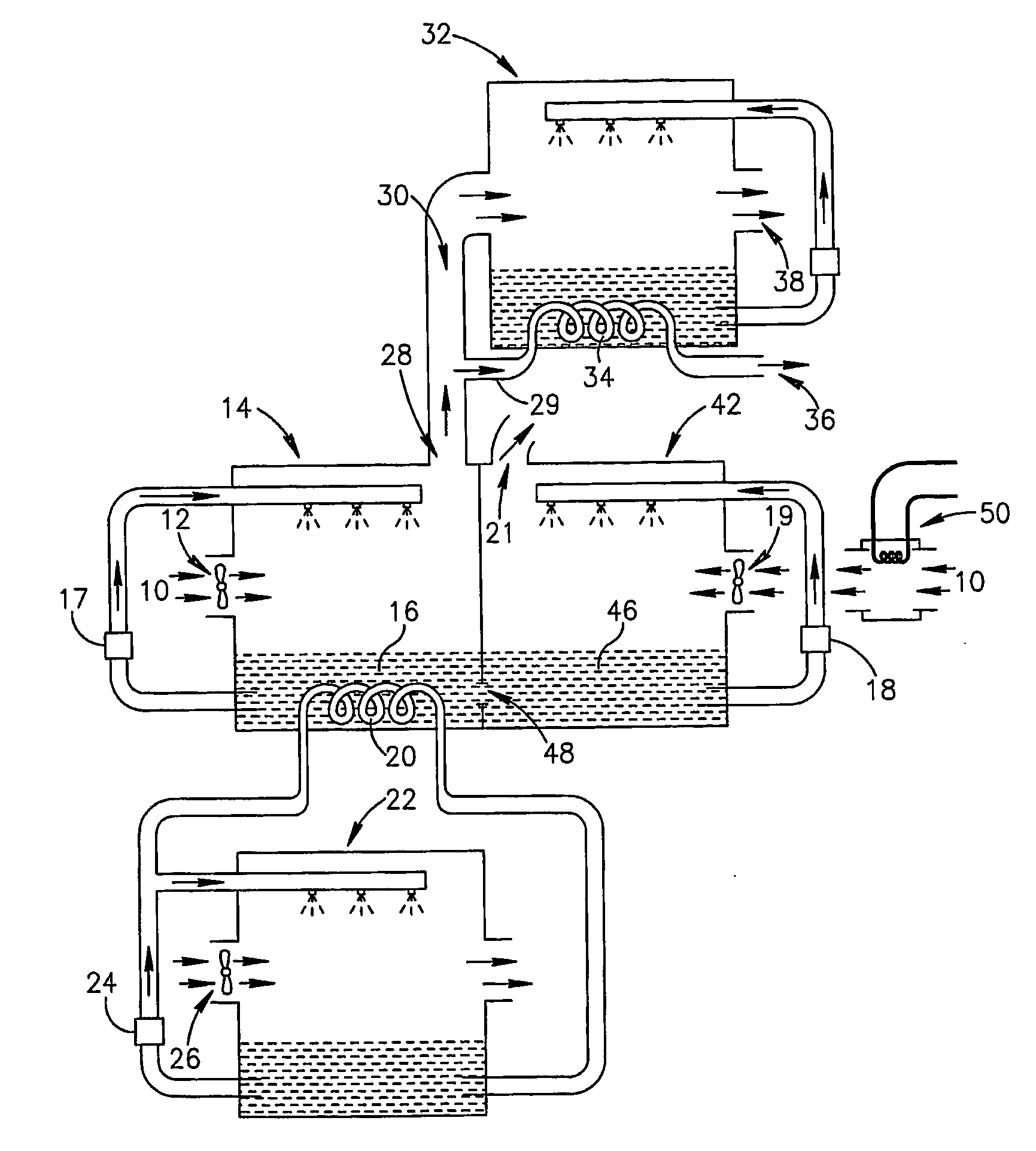
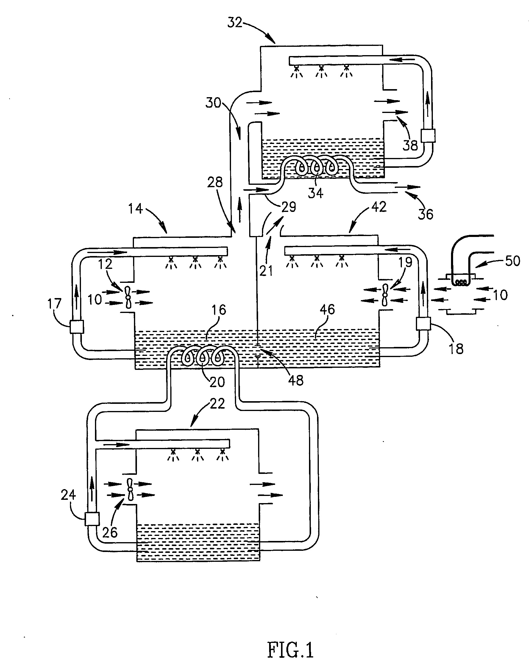
[0095] FIG. 1 schematically shows a combined dehumidifying / air-conditionin-g system, according to an exemplary embodiment of the invention. Warm and humid air 10 is drawn by an intake fan 12 into a dehumidifying chamber 14 which is associated with a reservoir 16 filled with liquid desiccant. Optionally, the dehumidifier uses a rotating wheel or belt or similar mechanism (not shown in FIG. 1), to circulate desiccant out of and into reservoir 16, as will be described in detail in FIG. 3, exposing the desiccant to the air and allowing the desiccant to absorb moisture from the air. Alternatively, the dehumidifier uses a prior art method of exposing the desiccant to the air, such as spraying, dripping, or wicking the desiccant. FIG. 1 shows a pump 17, which draws the desiccant out of reservoir 16, and drips or sprays it through the air. A regenerating chamber 42, adjacent to the dehumidifying chamber, has its own reservoir 46 of liquid desiccant, and its own pump 18, which draws desiccan...


PUM


Abstract

An air-conditioning system for conditioning air by removing heat and moisture from the air and transferring it to the environment, comprising: a dehumidifier (14) that produces dehumidified air and utilizes a liquid desiccant for drying; at least one non-desiccant fluid at a temperature lower than the temperature of the liquid desiccant; and at least one heat exchanger (20) in which the liquid desiccant is cooled by the at least one fluid.

Description

[0001] The present invention is related to the field of environmental control systems and more particularly, to the field of dehumidifiers, and systems which combine dehumidification and air conditioning.[0002] There have been two general approaches to the design of systems that combine air conditioning and dehumidification. In one approach, the air is cooled down to the dew point for the desired final moisture content, in order to remove all undesired moisture. Because this dew point is generally below the desired final air temperature, the air at this dew point must then be heated, usually by mixing it with air that is already in the room being air conditioned.[0003] In the second approach, the air is dehumidified, before cooling it, by exposing it to a desiccant, which absorbs moisture from the air. If the absorption of moisture by the desiccant takes place without any heat flow, i.e. at constant enthalpy, then the air will become hotter as it is dehumidified. The air must then b...

Claims


Application Information

Patent Timeline
IPC IPC(8): F24F3/14
CPCF24F3/1417F24F2003/144
Inventor FORKOSH, MORDECHAIFORKOSH, DANFORKOSH, TOMY
Owner DUCOOL
Why Eureka
Eureka Blog
Learn More