Carbon canister for use in evaporative emision control system of internal combustion engine

a technology of evaporative emission control and carbon canister, which is applied in electrical control, combustion-air/fuel-air treatment, and separation processes, etc., can solve the problems of carbon canister showing a considerable pressure loss between the first and second vapor trapping chambers, and increasing the amount of fuel vapors in the atmospher

Active Publication Date: 2004-12-30
MAHLE JAPAN LTD
View PDF5 Cites 30 Cited by
  • Summary
  • Abstract
  • Description
  • Claims
  • Application Information

AI Technical Summary

Problems solved by technology

Thus, undesired leakage of the fuel vapors into the atmosphere increases with passing of time.
However, even this improved carbon canister fails to provide the evaporative emission control system with a satisfied performance.
Actually, the car

Method used


Image

  • Carbon canister for use in evaporative emision control system of internal combustion engine
  • Carbon canister for use in evaporative emision control system of internal combustion engine
  • Carbon canister for use in evaporative emision control system of internal combustion engine

Examples


first embodiment

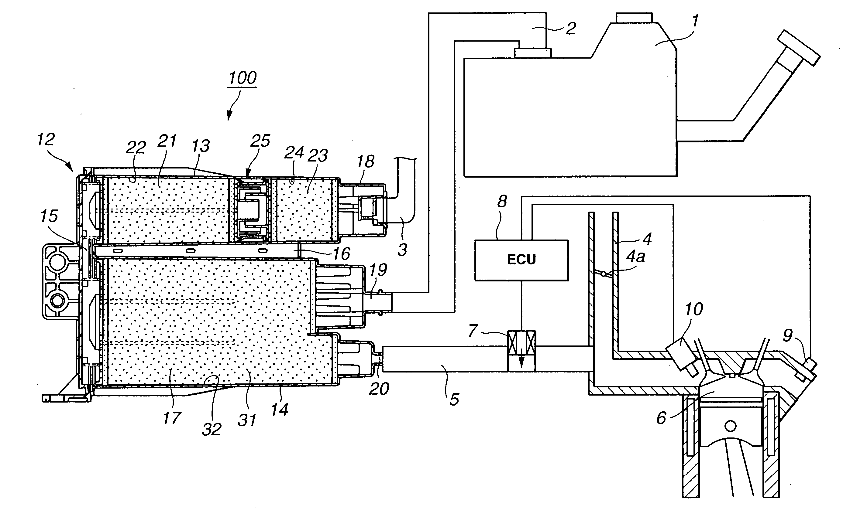
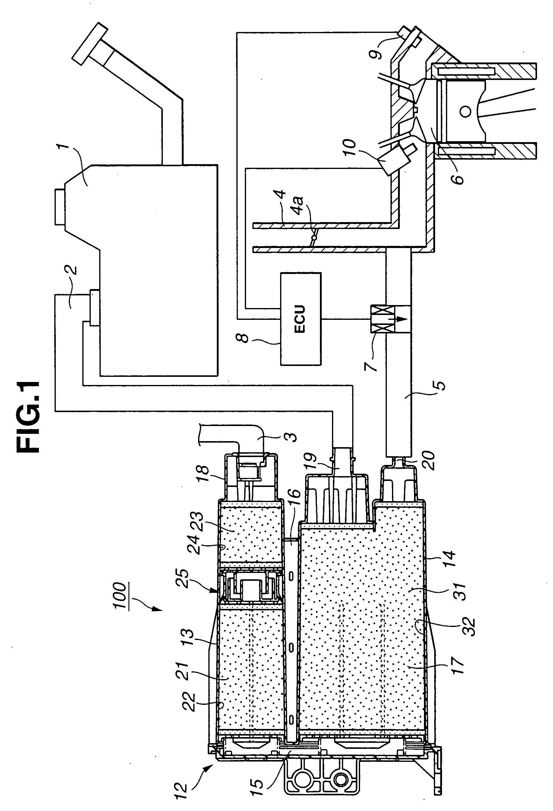
[0026] Referring to FIGS. 1 to 7, particularly FIGS. 1 and 2, there is shown a carbon canister 100 which is the present invention.

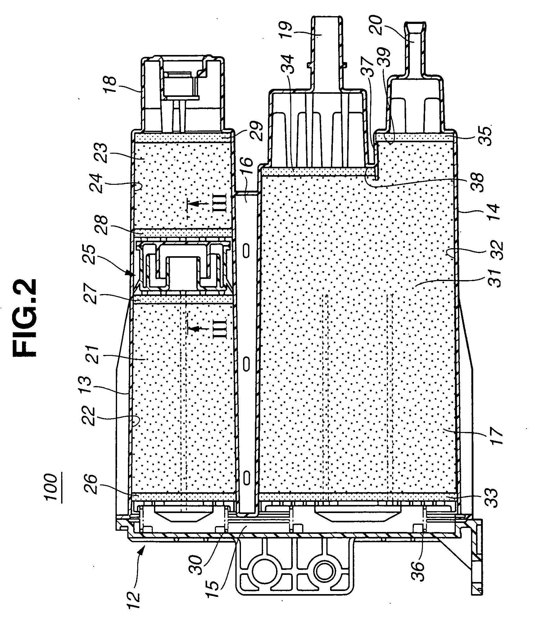
[0027] As is best shown in FIG. 2, carbon canister 100 comprises a generally cylindrical case 12 of a molded plastic, which includes a first hollow portion 13 and a second hollow portion 14 which are disposed on each other and extend in parallel with each other.

[0028] These two hollow portions 13 and 14 have respective left open ends which are integrally connected to spaced portions of a connector passage portion 15. Thus, a generally U-shaped passage 17 is defined in and by the plastic case 12, which comprises an interior of first hollow portion 13, that of connector passage portion 15 and that of second hollow portion 14.

[0029] As shown, first and second hollow portions 13 and 14 have a reinforcing rib 16 integrally interposed therebetween.

[0030] As shown in FIG. 1, first hollow portion 13 is formed at a right end thereof with an atmospheric air inlet p...

second embodiment

[0092] Referring to FIG. 8, there is shown a carbon canister 200 which is the present invention.

[0093] Since the second embodiment 200 is similar in construction to the above-mentioned first embodiment 100, only portions that are different from those of the first embodiment 100 will be described in detail in the following.

[0094] As is understood from the drawing, in second cylindrical chamber 24 at a position close to atmospheric air inlet port 18, there is disposed a fourth activated charcoal mass 52. More specifically, the fourth activated charcoal mass 52 is formed into a honeycomb structure and an eighth filter member 51 is put between the fourth activated charcoal mass 52 and second activated charcoal mass 23. That is, due to provision of eighth filter member 51 in second cylindrical chamber 24, a fourth cylindrical chamber 53 is defined in which the honeycomb type activated charcoal mass 52 is disposed.

[0095] In this second embodiment 200, the L / D rate of first cylindrical cha...

third embodiment

[0108] Referring to FIG. 11, there is shown a carbon canister 300 which is the present invention.

[0109] Since the third embodiment 300 is similar in construction to the above-mentioned first embodiment 100, only portions that are different from those of the first embodiment 100 will be described in detail in the following.

[0110] As is understood from the drawing, from atmospheric air inlet port 18, there extends a pipe 63 in which a fourth activated charcoal mass 52 is disposed. More specifically, the fourth activated charcoal mass 52 is formed into a honeycomb structure and sandwiched between ninth and tenth filter members 64 and 65. That is, in the pipe 63, there is defined a fourth cylindrical chamber 53 in which the honeycomb type activated charcoal mass 52 is disposed.

[0111] In this third embodiment 300, the L / D rate of first cylindrical chamber 22 and that of second cylindrical chamber 24 are both from about 2 to about 4. In third cylindrical chamber 32, the L / D rate is from a...


PUM


Abstract

First and second chambers are coaxially arranged and have substantially the same cross sectional area. First and second activated charcoal masses are respectively received in the first and second chambers. A labyrinth structure is arranged between respective first ends of the first and second chambers. An atmospheric air inlet port is provided by a second end of the second chamber. A third chamber is arranged beside the coaxially arranged first and second chambers. The third chamber has a first end positioned near a second end of the first chamber and a second end positioned near the second end of the second chamber. A third activated charcoal mass is received in the third chamber. A connector passage extends between the second end of the first chamber and the first end of the third chamber to provide a fluid connection between the first and third chambers. A fuel vapor inlet port is provided by the second end of the third chamber, and a fuel vapor outlet port is also provided by the second end of the third chamber.

Description

[0001] 1. Field of the Invention[0002] The present invention relates in general to an evaporative emission control system of an internal combustion engine, and more particularly to a carbon canister which is practically employed in the evaporative emission control system.[0003] 2. Description of the Related Art[0004] Hitherto, for suppressing atmospheric pollution from motor vehicles powered by internal combustion engines, various evaporative emission control systems have been proposed and put into practical use. Some of them are of a type which employs a carbon canister to capture any fuel vapors (viz., HC) coming from the fuel tank. That is, the carbon canister prevents the vapors from escaping into the atmosphere. The carbon canister generally comprises a canister case which is filled with activated charcoal mass which adsorbs the fuel vapors. The canister case is formed at one end with an atmospheric air inlet port and at the other with both a fuel vapor inlet port and a fuel va...

Claims


Application Information

Patent Timeline
IPC IPC(8): F02M25/08
CPCF02M25/0854F02M25/0872F02M2025/0845
Inventor OGAWA, MASAHIRO
Owner MAHLE JAPAN LTD
Why Eureka
Try Eureka