Device for jetting droplets of a particle filled viscous medium

a technology of viscous medium and droplet jet, which is applied in the direction of coating, blast furnace components, blast furnaces, etc., can solve the problems of unintentional interruption of the series of consecutive droplets of solder paste jetted from the device, generating droplets of a predetermined size, and mechanical causes

a technology of viscous medium and droplet jet, which is applied in the direction of coating, blast furnace components, blast furnaces, etc., can solve the problems of unintentional interruption of the series of consecutive droplets of solder paste jetted from the device, generating droplets of a predetermined size, and mechanical causes

US20040262824A1Active Publication Date: 2004-12-30MYCRONIC

Image

  • Device for jetting droplets of a particle filled viscous medium
  • Device for jetting droplets of a particle filled viscous medium
  • Device for jetting droplets of a particle filled viscous medium

Examples


Embodiment Construction

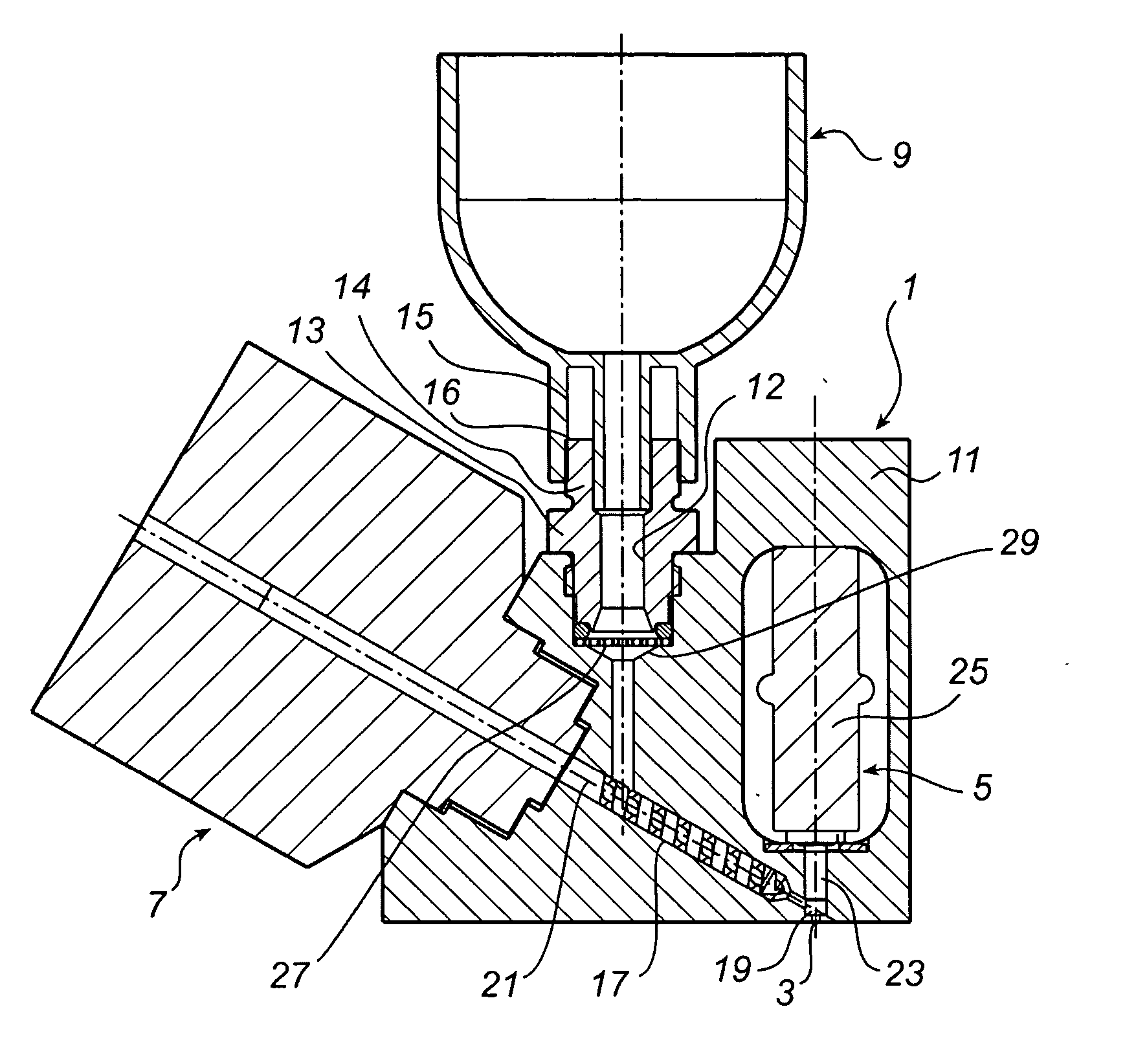
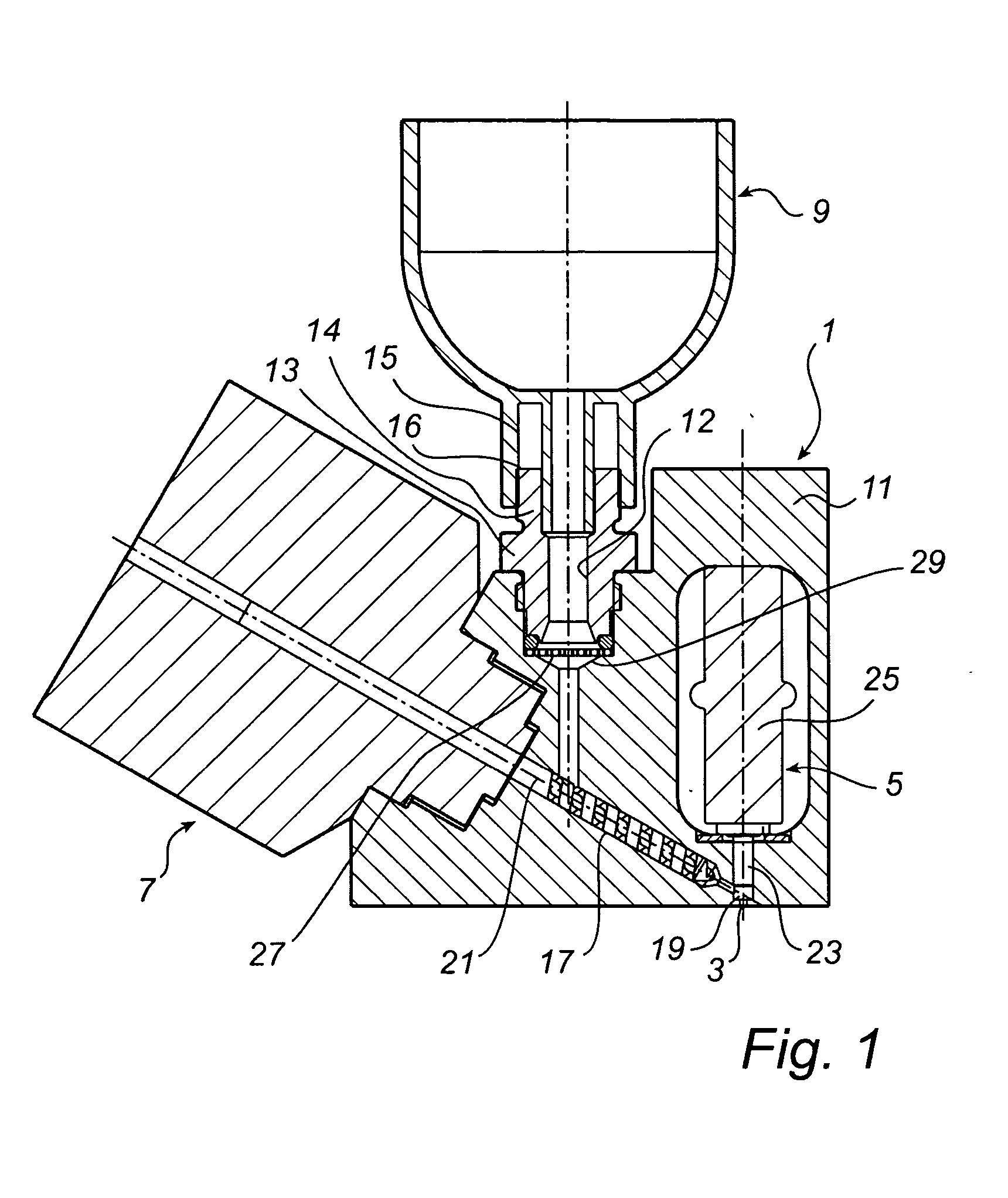
[0019] In FIG. 1 the principal structure of an embodiment of a device according the present invention is disclosed. The device 1 comprises a nozzle 3, through which solder paste is ejected, an ejection mechanism 5, a feeding mechanism 7, connected to the ejection mechanism for feeding solder paste into the ejection mechanism, and a solder paste container 9. All those parts are mounted in a body 11 having necessary recesses, borings etc., for mounting the different parts and for guiding the solder paste from the container 9 to the nozzle 3. The path which the solder paste follows on its way to the nozzle comprises an inlet duct 12 extending from a container holder 13, where an outlet portion 15 of the container 9 is received, to the feeding mechanism 7, and more specifically to a feeding tube 17, which extends to the ejection mechanism 5, and more specifically to an eject chamber 19.

[0020] The container holder 13 has a cylindrical end portion 14, which has an internal thread. The out...


PUM

PropertyMeasurementUnit
viscousaaaaaaaaaa
sizeaaaaaaaaaa
viscous propertiesaaaaaaaaaa

Abstract

This invention relates to a device for jetting droplets of a particle filled viscous medium. The device has a nozzle, an eject mechanism connected to the nozzle, a medium feeding mechanism connected to the eject mechanism, a particle filled viscous medium container connected to the medium feeding mechanism, and a filter arranged between an outlet of the particle filled viscous medium container and the medium feeding mechanism.

Description

[0001] This invention relates to a device for jetting droplets of a particle filled viscous medium, such as solder paste.TECHNICAL BACKGROUND[0002] In the non-contact viscous medium dispensing technology called jetting, which has been developed in the course of the recent years, a central issue is how to generate droplets of a predetermined size at a predetermined pace. In many respects this technology is superior to other available dispensing technologies. However, at an early stage, when jetting viscous medium containing a substantial amount of particles, such as solder paste, a problem encountered was an unexpected interference and unintentional interruption of the series of consecutive solder paste droplets jetted from the device.[0003] Since the solder paste is a most special type of medium consisting of a solder powder, i.e. small metal grains, solved in a viscous flux, and since the jetting technology is rather an extreme variety of dispensing, it was initially presumed that ...

Claims


Application Information

Patent Timeline
30 Dec 2004
Publication
US20040262824A1
IPC
B05C5/00; B05C5/02; B05C11/10
CPC
B05C5/02; B05C11/1034
Inventors
ANDERSSON; BERG, JOHAN