Magnetic resonance imaging interference immune device

Inactive Publication Date: 2004-12-30
MEDTRONIC INC
View PDF4 Cites 141 Cited by
  • Summary
  • Abstract
  • Description
  • Claims
  • Application Information

AI Technical Summary

Benefits of technology

0025] A first aspect of the present invention is a voltage compensation unit for reducing the effects of induced voltages upon a device to a safe level. The voltage compensation unit includes a sensing circuit to sense voltages induced in conductive components of the device

Problems solved by technology

1. Erroneous signals to be induced/generated in a sensing lead or device or circuit;
2. Damage to electronics; and/or
3. Harmful stimulation of tissue, e.g. heart muscle, nerves, etc.
As noted above, the use of the MRI process with patients who have implanted medical assist devices; such as cardiac assist devices or implanted insulin pumps; often presents problems.
Since the sensing systems and conductive elements of these implantable devices are responsive to changes in local electromagnetic fields, the implanted devices are vulnerable to external sources of severe electromagnetic noise, and in particular, to electromagnetic fields emitted during the magnetic resonance imagin

Method used


Image

  • Magnetic resonance imaging interference immune device
  • Magnetic resonance imaging interference immune device
  • Magnetic resonance imaging interference immune device

Examples


Example

[0082] The present invention will be described in connection with preferred embodiments; however, it will be understood that there is no intent to limit the present invention to the embodiments described herein. On the contrary, the intent is to cover all alternatives, modifications, and equivalents as may be included within the spirit and scope of the present invention as defined by the appended claims.

[0083] For a general understanding of the present invention, reference is made to the drawings. In the drawings, like reference have been used throughout to designate identical or equivalent elements. It is also noted that the various drawings illustrating the present invention are not drawn to scale and that certain regions have been purposely drawn disproportionately so that the features and concepts of the present invention could be properly illustrated.

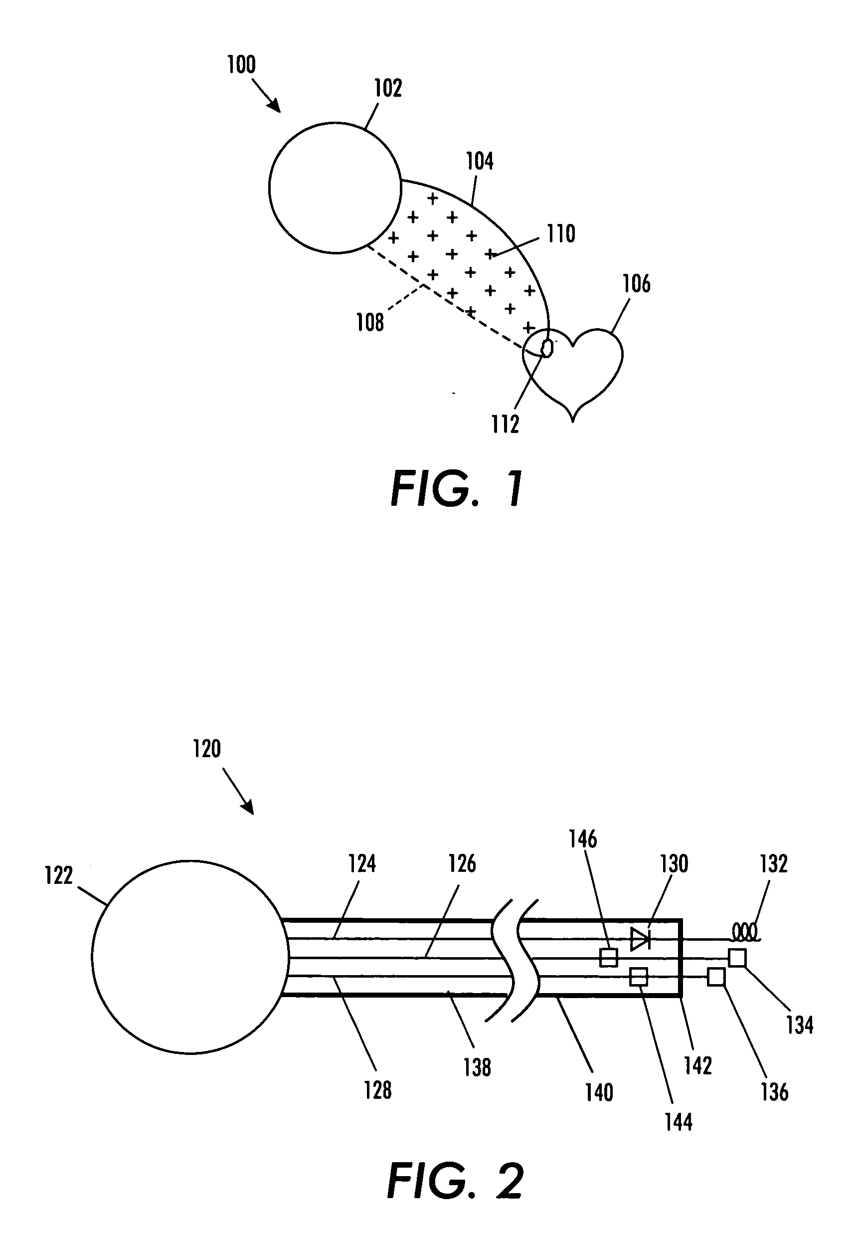
[0084] FIG. 1 is a schematic showing a typical pacemaker arrangement 100. The pacemaker comprises a pulse generator canister 102 ...


PUM


Abstract

A voltage compensation unit reduces the effects of induced voltages upon a device having a single wire line. The single wire line has balanced characteristic impedance. The voltage compensation unit includes a tunable compensation circuit connected to the wire line. The tunable compensation circuit applies supplemental impedance to the wire line. The supplemental impedance causes the characteristic impedance of the wire line to become unbalanced, thereby reducing the effects of induced voltages caused by changing magnetic fields.

Description

PRIORITY INFORMATION[0001] This application claims priority under 35 U.S.C. .sctn.119(e) from U.S. Provisional Patent Application, Ser. No. 60 / 482,177, filed on Jun. 24, 2003. The entire content of U.S. Provisional Patent Application, Ser. No. 60 / 482,177 is hereby incorporated by reference.CROSS REFERENCE TO RELATED PATENT APPLICATIONS[0002] The subject matter of co-pending U.S. patent application Ser. No. 09 / 885,867, filed on Jun. 20, 2001, entitled "Controllable, Wearable MRI-Compatible Cardiac Pacemaker With Pulse Carrying Photonic Catheter And VOO Functionality"; co-pending U.S. patent application Ser. No. 09 / 885,868, filed on Jun. 20, 2001, entitled "Controllable, Wearable MRI-Compatible Cardiac Pacemaker With Power Carrying Photonic Catheter And VOO Functionality"; co-pending U.S. patent application Ser. No. 10 / 037,513, filed on Jan. 4, 2002, entitled "Optical Pulse Generator For Battery Powered Photonic Pacemakers And Other Light Driven Medical Stimulation Equipment"; co-pend...

Claims


Application Information

Patent Timeline
IPC IPC(8): G01R33/28
CPCA61B2562/222A61N1/05A61N1/37A61N1/3718A61N2001/086G01R33/285G01R33/288G01R33/34084H03H7/42A61N1/086
Inventor GRAY, ROBERT W.SIMPSON, PAUL G. IIIWEINER, MICHAEL L.
Owner MEDTRONIC INC
Why Eureka
Try Eureka