Pressure sensor

Inactive Publication Date: 2005-01-06
TECHNO EXCEL CO LTD
View PDF0 Cites 14 Cited by
  • Summary
  • Abstract
  • Description
  • Claims
  • Application Information

AI Technical Summary

Benefits of technology

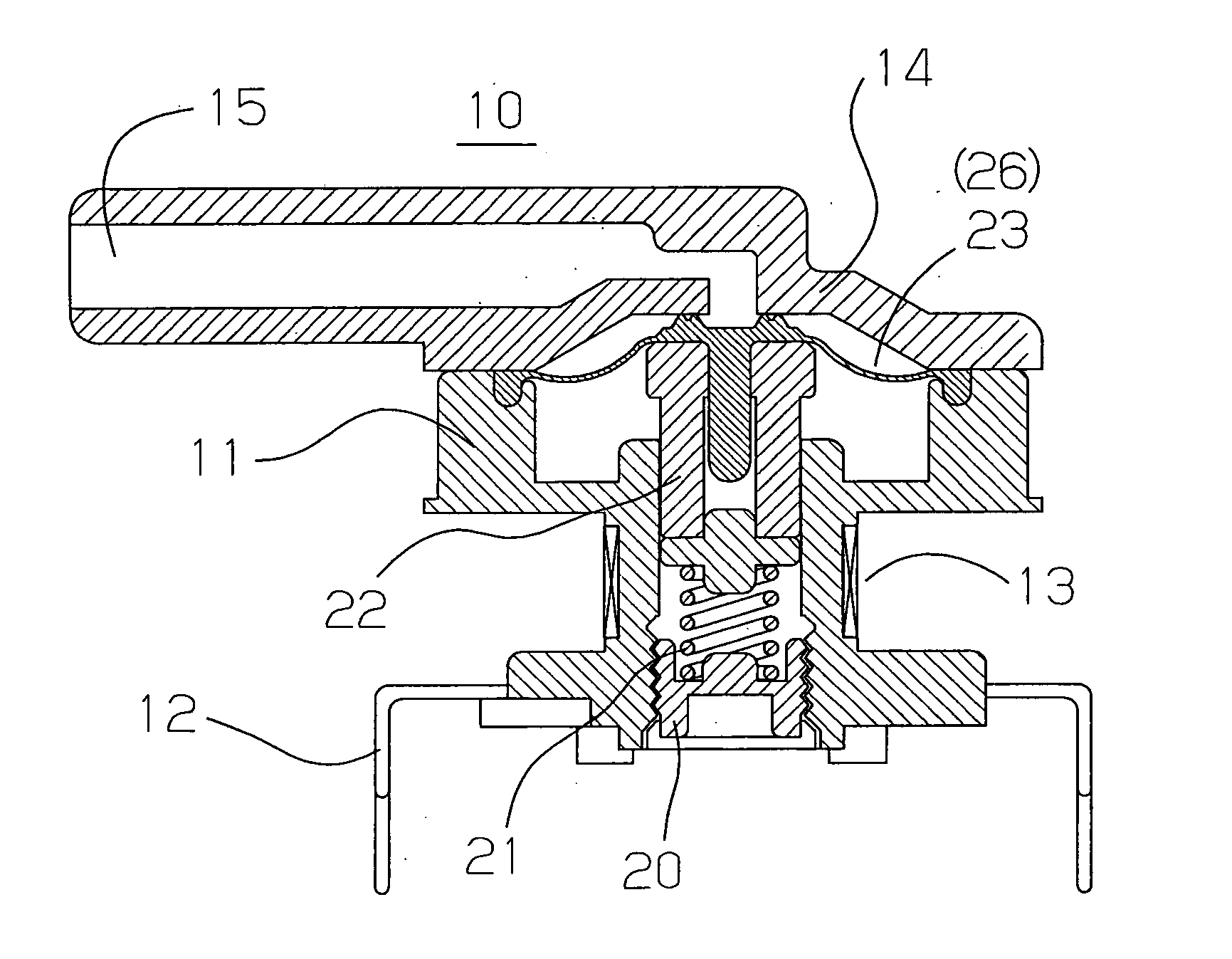
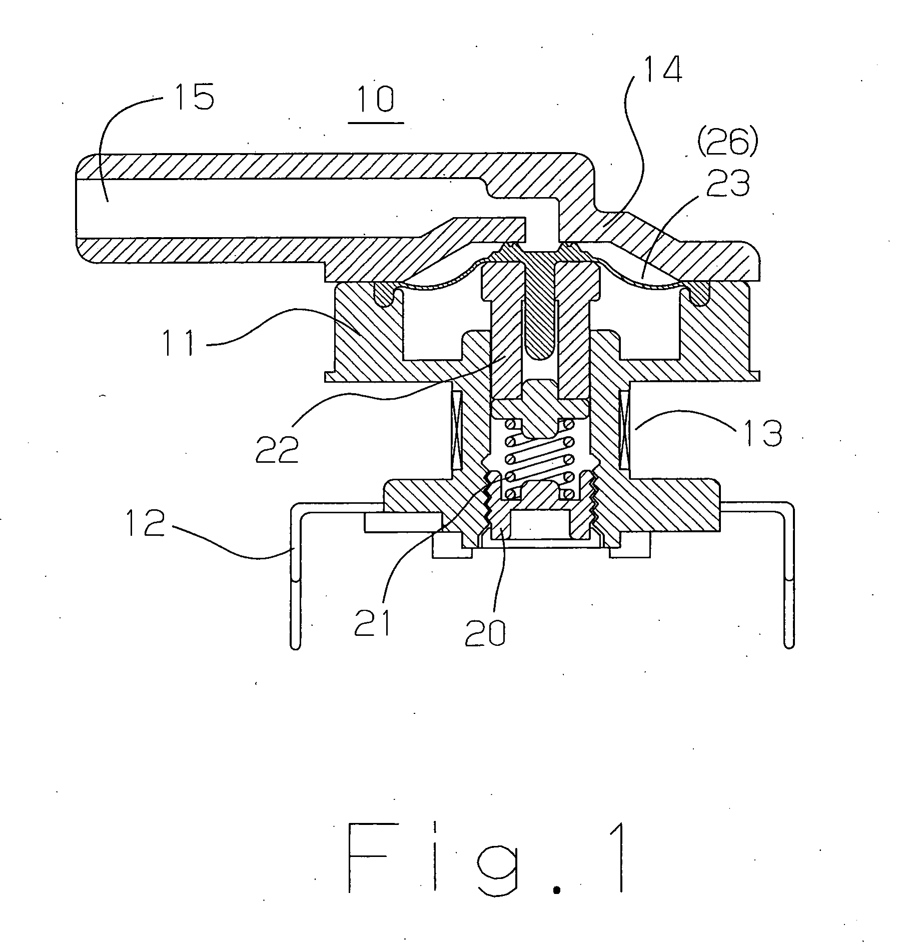
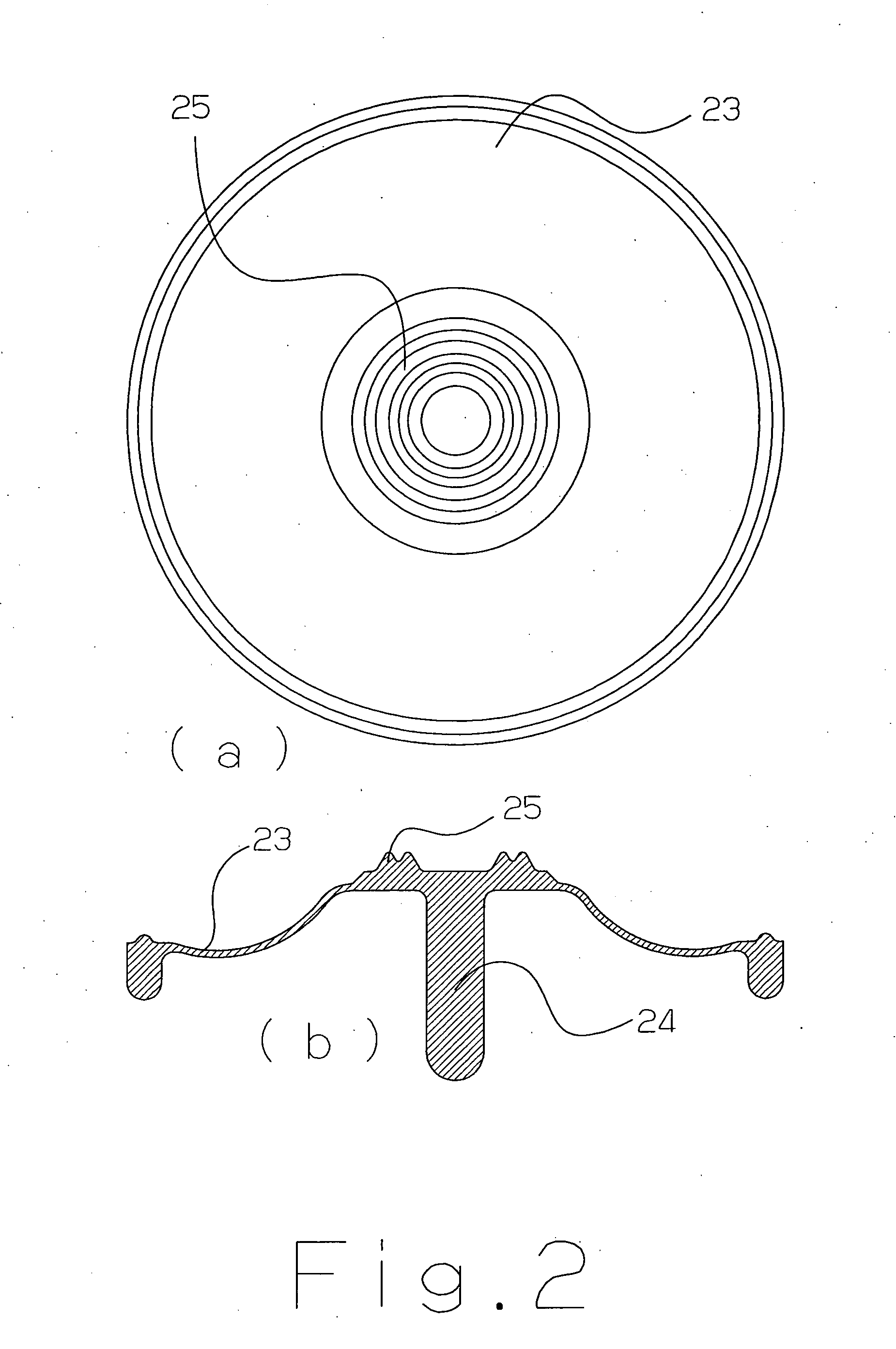
By forming plural reinforcing ribs into intermittent ring-shaped, the pressure-applying area/volume of a diaphragm when plural ring-shaped reinforcing ribs are in contact with said cover (no load condition when no pressure is applied to the diaphragm) and the pressure-applying area/volume of a diaphragm when said diaphragm is apart from said cover (diaphragm is displaced due to pressure load) become equal, which takes an effect that there is no unstable range (non-linear portion) in the relation between pressure and diaphragm displacement due to pressure load.
The objective to eliminate the unstable range (non-linear portion) in the relation between pressure and diaphragm displ

Problems solved by technology

However, although it is possible to form small bosses if said cover has a large diam

Method used


Image

  • Pressure sensor
  • Pressure sensor
  • Pressure sensor

Examples


Embodiment Construction

Problems to be Solved by the Invention

There is a description in Japan's Published Unexamined Patent Application No. 23394 / 99, from the 38th line of page 4, item 6 to the second line of page 5, item 7 that “. . . also, the retaining part 14c is thickly formed to improve the total rigidity, and it is possible to further improve the rigidity of the retaining part 14c by providing reinforcing ribs 14d on a pressure-applying surface of the retaining part 14c. By thus improving the rigidity of the retaining part 14c, it becomes possible to prevent the diaphragm 14 from degrading its planarity by deformation of the retaining part 14c as the diaphragm displaces, to move the core 16 linearly along the direction of the axis line of the diaphragm 14, and to prevent the core 16 from leaning during the movement. Because of these, accurate displacement measurement becomes possible, which consequently enables accurate pressure measurement. Figuration of the reinforcement ribs 14d may be formed ...


PUM


Abstract

To improve the characteristics of a portion which can be represented by an approximate first-order line (so-called linearity) in the relation between pressure and diaphragm displacement. To equalize the pressure-applying area/volume of a diaphragm when plural ring-shaped reinforcement ribs are in contact with said cover (no load condition when no pressure is applied to the diaphragm) and the pressure-applying area/volume of a diaphragm when said diaphragm is apart from said cover (the diaphragm is displaced due to pressure load).

Description

FIELD OF INVENTION This invention mainly relates to a pressure sensor that is mounted on a printed circuit board used for washing machines, bathtub units, air conditioners, dishwashers, etc. More particularly, for a diaphragm that converts pressure into displacement, this invention relates to the improvement of the characteristics of the portion which can be represented by an approximate first-order line (so called “linearity”) in the relation between pressure and diaphragm displacement. BACKGROUND ART A pressure sensor designed to be mounted on a printed circuit board is known to be comprising: a body, wherein tab terminals for connector connection are insert-molded, or wherein coil terminals-cum-soldering fixed terminals which are inserted into a printed circuit board are insert-molded; a coil spring adjusting screw which is screwed into said body; a coil which is wound around said body; a magnetic body which moves relative to said coil; a diaphragm which has a support for ...

Claims


Application Information

Patent Timeline
IPC IPC(8): G01L9/10G01L7/08
CPCG01L9/007G01L9/0044
Inventor SHIRAI, SUSUMUMAKI, KATSUMI
Owner TECHNO EXCEL CO LTD
Why Eureka
Try Eureka