Knee bolster

a knee bolster and knee technology, applied in the field of knee bolsters, can solve the problems of inconvenient configuration of the conventional knee bolster, inability to reliably receive the impact of the knees of both the seated occupant m and the seated occupant f, and inability to meet the needs of a woman of relatively small siz

Active Publication Date: 2005-01-06
MITSUBISHI MOTORS CORP
View PDF10 Cites 13 Cited by
  • Summary
  • Abstract
  • Description
  • Claims
  • Application Information

AI Technical Summary

Benefits of technology

[0010] It is therefore an object of the present invention to provide a knee bolster capable of absorbing load received from the knees of seated occupants of various physical sizes.

Problems solved by technology

The conventional knee bolster, however, is not configured suitably for a woman of relatively small size.
Also, if the knee bolster is moved downward to receive load applied to the seated occupant F, impact cannot be satisfactorily absorbed since a load receiving part of the knee bolster has moved downward relative to the knees of a seated occupant of large size such as the seated occupant M.
If the knee bolster configured for the seated occupant M is only installed as a fixing device, it is impossible to reliably receive impact received from the knees of both the seated occupant M and the seated occupant F.
Further, if only one knee bolster is used to absorb impact received from the knees of both seated occupants M and F, the knee bolster needs to be larger in size, making it impossible to ensure enough space under the feet of the seated occupants M and F. At the same time, the knee bolster will increase in cost and weight.

Method used


Image

  • Knee bolster
  • Knee bolster
  • Knee bolster

Examples


Embodiment Construction

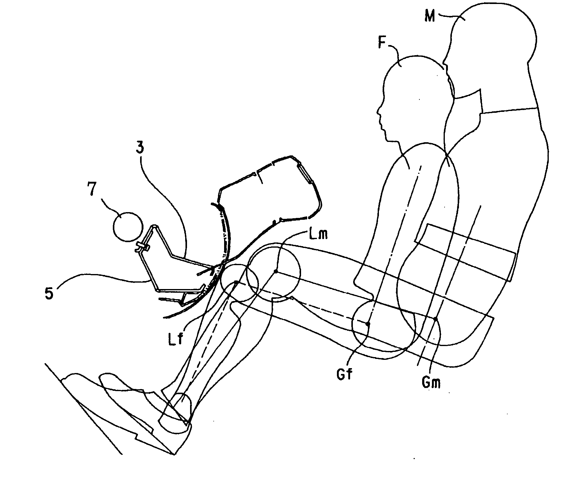
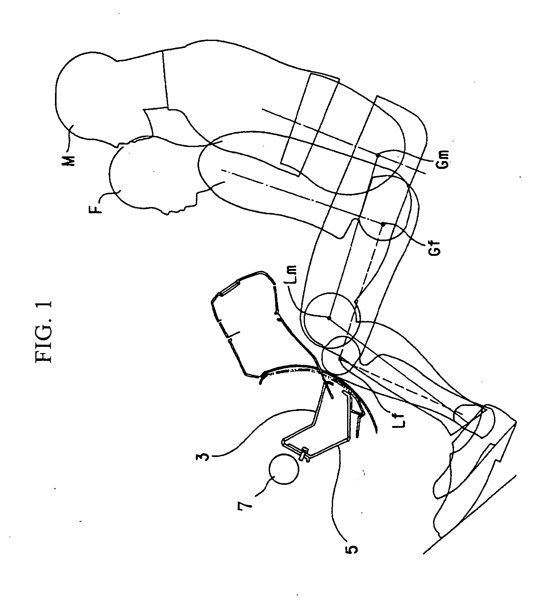
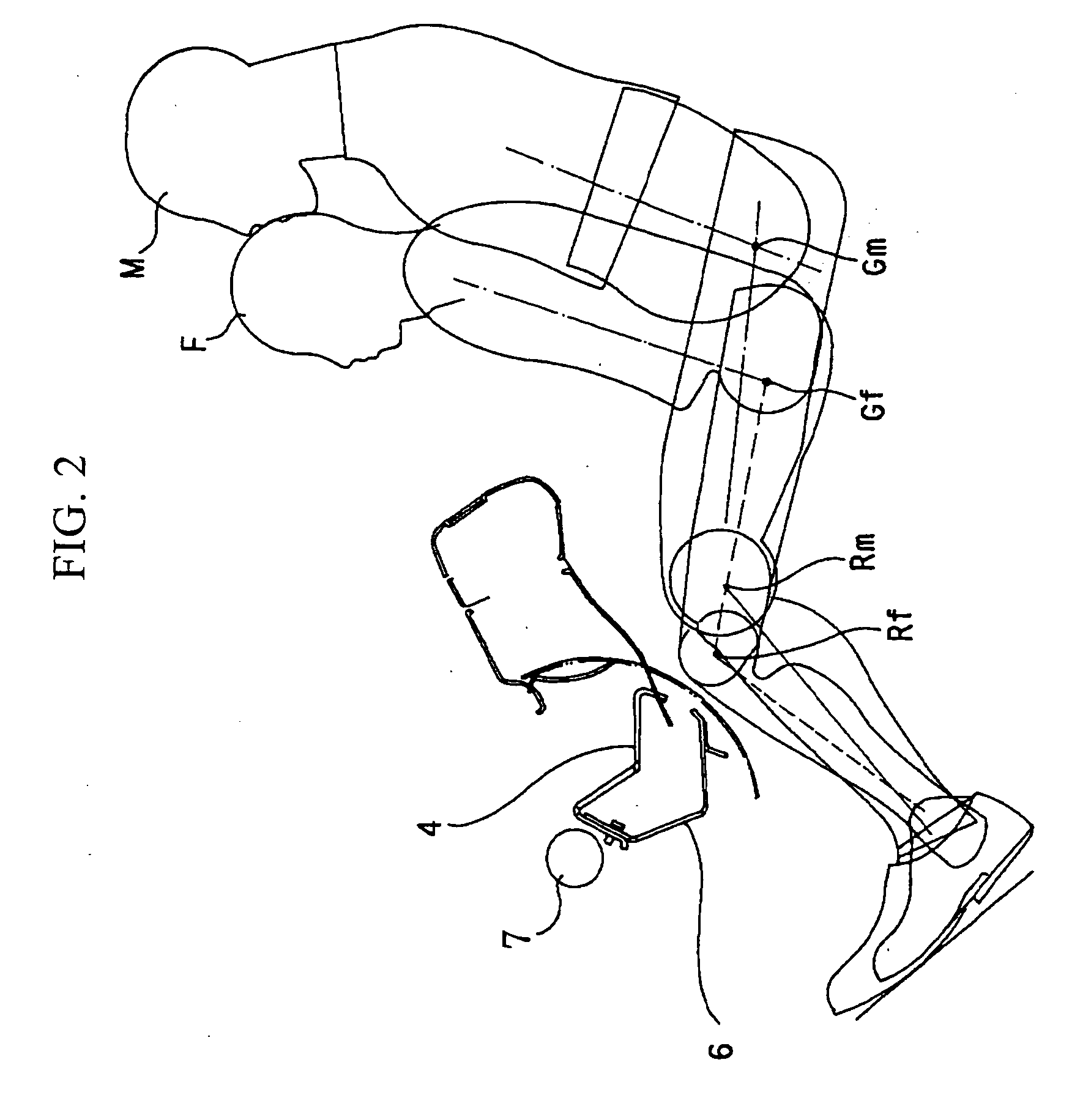
[0020] The present invention will now be described in detail with reference to the drawings showing a preferred embodiment thereof.

[0021] When driving a vehicle, an occupant adjusts his / her seated position by adjusting the position of a seat installed in the vehicle. Examples of seat adjustments include a sliding adjustment in which a seat is slid forward and backward in the direction of vehicle length, a height adjustment in which the height is adjusted by moving a seat in the direction of vehicle height, a reclining adjustment in which a seat is reclined by adjusting the angle of a seat back, and a vertical adjustment in which a headrest installed in an upper part of a seat back to set the position of an occupant's head is moved in the direction of vehicle length or in the direction of vehicle height. Due to variations in physical size of occupants, there are an indefinitely large number of seated positions, but in the present embodiment, it is assumed that the seated occupant M ...


PUM


Abstract

A knee bolster whose load receiving parts absorb load from the knees of seated occupants of various physical sizes is provided. An upper knee bolster and a lower knee bolster are each provided with a load receiving part that receives load from the knees of a seated occupant who moves forward in the direction of vehicle length in the event of a vehicle head-on collision, and a deforming part that moves the load receiving part, which has been deformed by the load, forward in the direction of vehicle length.

Description

CROSS-REFERENCE TO REFERENCE TO RELATED APPLICATION [0001] This application incorporates by reference the subject matter of Application No. 2003-148704, filed in Japan on May 27, 2003, on which a priority claim is based under 35 U.S.C. § 119 (a) BACKGROUND OF THE INVENTION [0002] (1) Field of the Invention [0003] The present invention relates to a knee bolster for a vehicle, which absorbs load received from the knees of a seated occupant who moves forward in the direction of vehicle length in the event of vehicle collision. [0004] (2) Description of Related Art [0005] In recent years, the safety performance of vehicles has been significantly improved. At the same time, safety standards have been reviewed, and regulations have been gradually tightened. Conventionally, in conformity with standards, a dummy which can cover a man of relatively large size (hereinafter referred to as “the seated occupant M”) has been used for vehicle head-on collision experiments. Recently, due to e.g., r...

Claims


Application Information

Patent Timeline
Patent Type & Authority Applications(United States)
IPC IPC(8): B60R21/00B60R21/045
CPCB60R2021/0051B60R21/045
Inventor MURAMATSU, MUTSUOHARA, SHINJIMABASHI, YOHEIKISHIMOTO, TSUNENORIKATO, TOYOAKI
Owner MITSUBISHI MOTORS CORP
Why Eureka
Try Eureka